Auxiliary wing and flap assembly for an aircraft

a technology of auxiliary wings and flaps, applied in the field of aircraft, can solve the problems of inability to obtain quickly adequate landing space, difficulty and many times almost impossible, and the aircraft may be coming down at too steep of an angle to perform any kind of landing, so as to shorten the landing distance and increase the lift

Inactive Publication Date: 2010-06-22
NAHAS ROGER A
View PDF7 Cites 22 Cited by
  • Summary
  • Abstract
  • Description
  • Claims
  • Application Information

AI Technical Summary

Benefits of technology

[0010]The basic embodiment of the present invention is directed to an auxiliary wing and flap assembly for an aircraft which utilizes a split flap mounted on a first hinge axis on the aircraft wing with the split flap being located directly adjacent the trailing edge of the wing. The split flap is to be movable between a first retracted position and an extended position with the first retracted position locating the split flap against the aircraft wing and the extended position locating the split flap substantially transverse to the aircraft wing. An auxiliary wing assembly is mounted by a hinge connection to the aircraft wing with this hinge connection being located intermediate the leading edge and the first hinge axis. The auxiliary wing defines an airfoil-shaped member mounted by a bracket assembly to the aircraft wing with the auxiliary wing assembly being movable between a second retracted position and a deployed position. The second retracted position locates the airfoil shaped-member against the aircraft wing. The deployed position locates the airfoil-shaped member transversely to the aircraft wing. When in the deployed position there is created a longitudinal air gap area located between the airfoil-shaped member and the aircraft wing. The split flap, when located in the extended position, and the auxiliary wing, when located in the deployed position will cause the aircraft when flying to appreciably slow and lift in order to substantially shorten the landing distance when landing of the aircraft and also function to substantially increase lift when taking off of the aircraft.

Problems solved by technology

Small aircraft that have only a single engine have a disadvantage when compared to multi-engine aircraft.
If the single engine becomes inoperative during flight, obtaining quickly adequate landing space is, at times, difficult and many times almost impossible.
Also, the aircraft may be coming down to the ground at too steep of an angle to perform any kind of a “soft landing”.
It is for this reason that many times operators of small aircraft are killed or severely injured upon an engine problem occurring with the aircraft during flight.
This means that in a congested area where the airport is surrounded with buildings and houses that utilizing of a shallow angle of four to six degrees constitutes a rather dangerous situation.
Utilizing of an extended runway length is again a potentially dangerous situation.

Method used


Image

  • Auxiliary wing and flap assembly for an aircraft
  • Auxiliary wing and flap assembly for an aircraft

Examples


Embodiment Construction

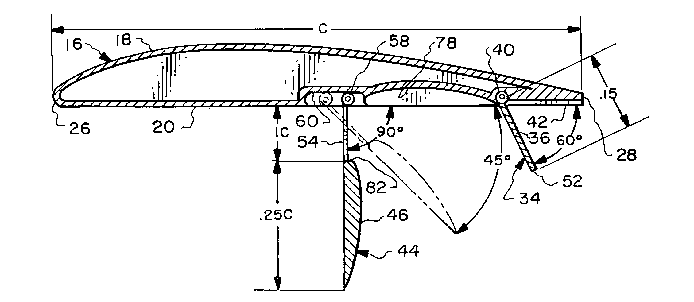
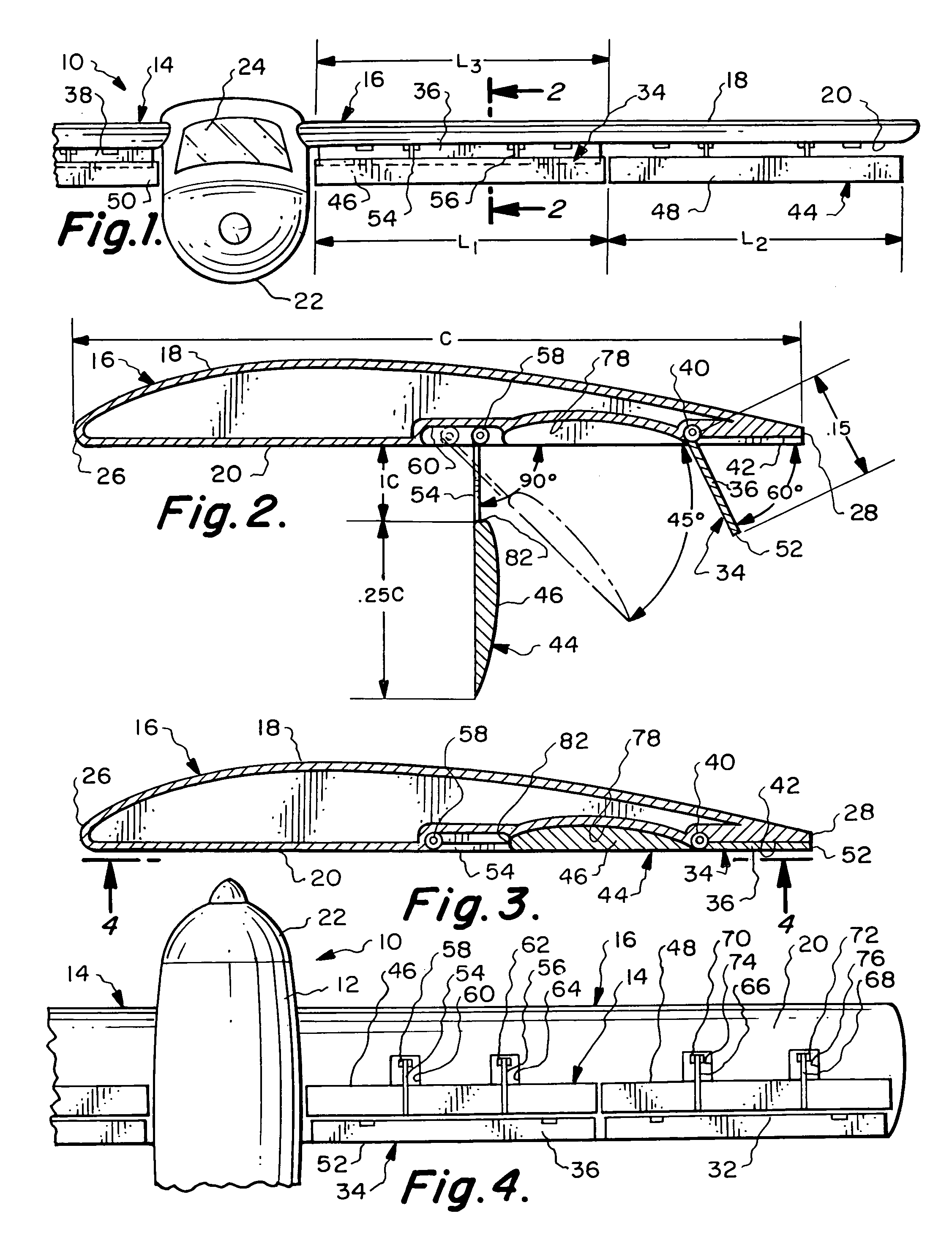
[0021]Referring particularly to the drawing, there is shown an aircraft 10 that has a fuselage 12, a right wing 14 and a left wing 16. The structure of the present invention is going to be discussed in relation to the left wing 16. However, it is considered to be within the scope of this invention that the same structure will be employed in conjunction with the right wing 14. Mounted on the lower end of the fuselage is a conventional landing gear of some sort, which is not shown.

[0022]The wing 16 is airfoil-shaped and has a top surface 18 and a bottom surface 20. The front of the fuselage 12 is formed into a nose 22 and above the nose 22 is located a windshield 24. The aircraft wing 16 has a leading edge 26 and a trailing edge 28. It is to be understood that when the aircraft 10 is flown that the leading edge 26 is first to move through the air. The aircraft wing 16 has a chord length which is shown as C in FIG. 2. The aircraft wing 16 has a chord axis which extends between the tip ...


PUM


Abstract

An auxiliary wing and flap assembly for an aircraft which is to be extendable from a retracted position to a deployed position. Relative to the chord of the wing, the split flap is located directly adjacent the trailing edge of the wing with the auxiliary wing assembly being located at approximately the mid length of the chord of the wing. A split flap assembly extends approximately one-half the length of the aircraft wing with the auxiliary wing assembly extending the total length of the aircraft wing. The split flap is extendable to assume approximately a sixty degree angle relative to the bottom surface of the aircraft wing while the auxiliary wing assembly is extendible to assume a maximum of ninety degree angle relative to the bottom surface of the aircraft wing. The chord length of the split flap is equal to approximately 0.15 of the chord length of the aircraft wing while the auxiliary wing assembly has an airfoil-shaped member that has a chord length of approximately 0.25 the chord length of the aircraft wing.

Description

BACKGROUND OF THE INVENTION[0001]1. Field of the Invention[0002]This invention relates to aircraft and more particularly to a new and novel auxiliary wing and flap assembly which permits the aircraft to land and take off in a substantially shorter distance while maintaining a high cruising speed.[0003]2. Description of the Related Art[0004]The use of a split flap in aircraft is exceedingly conventional. It is common that the split flaps are to be located at the trailing edge of the wing of the aircraft. The primary purpose of the split flap is to increase lift and also decrease the speed of the aircraft. Generally, these split flaps are used during landing of the aircraft.[0005]The present invention is to be discussed primarily in conjunction with small aircraft. The present invention is of particular advantage in conjunction with small aircraft. However, it is considered to be within the scope of this invention that the present invention could be utilized in conjunction with larger...

Claims


Application Information

Patent Timeline
Patent Type & Authority Patents(United States)
IPC IPC(8): B64C3/00
CPCB64C9/20B64C9/323B64C9/32
Inventor NAHAS, ROGER A.
Owner NAHAS ROGER A
Why Eureka
Try Eureka