Unlock instant, AI-driven research and patent intelligence for your innovation.

Circuit and method for generating a PWM control signal for a class-D amplifier

a class-d amplifier and control signal technology, applied in the field of class-d amplifiers, can solve the problems of low efficiency of conventional audio power amplifiers, large physical amplifiers, and reduced efficiency

Inactive Publication Date: 2010-06-22
RICHTEK TECH
View PDF4 Cites 4 Cited by
  • Summary
  • Abstract
  • Description
  • Claims
  • Application Information

AI Technical Summary

Problems solved by technology

Conventional audio power amplifiers suffer from low efficiency, and this causes these devices to generate heat that must be removed by large heat sinks and thereby causes the physical amplifiers to be quite large.
Higher switching frequencies can reduce distortion but also result in lower efficiency due to the extra transitions in the output waveform.
However as is well known, the class-D amplifiers have electromagnetic interference (EMI) problem, as do the majority of switching power management devices, since they are derived from switching power supply configuration.
This large amplitude results in large ripple of the load current and therefore, there is always need for an external filter to remove the high frequency switching carrier.
This filter typically includes at least two high current inductors and three capacitors which are expensive and consume undesirable amounts of space.

Method used


Image

  • Circuit and method for generating a PWM control signal for a class-D amplifier
  • Circuit and method for generating a PWM control signal for a class-D amplifier
  • Circuit and method for generating a PWM control signal for a class-D amplifier

Examples


Embodiment Construction

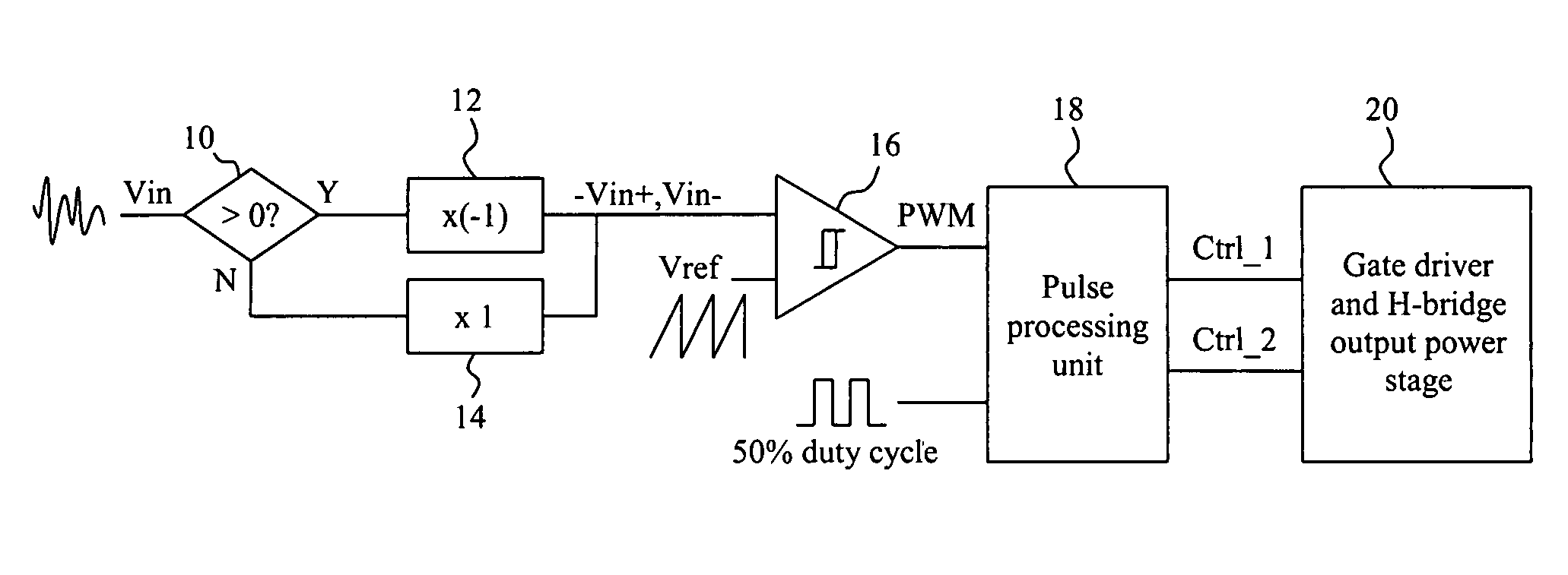
[0019]FIG. 3 is a block diagram of a first embodiment according to the present invention. This single-end input class-D amplifier has an input Vin to receive an input signal. When a single-end input signal Vin is detected, its polarity is to be identified first. This is done by a polarity identifying circuit 10 in a pre-processing unit. For example, the polarity identifying circuit 10 may include a comparator to compare the single-end input signal Vin with a direct current (DC) voltage, for example 0 volt. The pre-processing unit further includes an inverter 12 and a bypass circuit 14, both coupled to the polarity identifying circuit 10. The input signal Vin would be inverted by the inverter 12 if it is positive and if it is negative, it would be bypassed to combine with the output of the inverter 12. Therefore, the single-end input signal Vin is pre-processed by the pre-processing unit into a negative single-end input signal for a hysteresis comparator 16 to compare with a carrier ...


PUM


Abstract

In a class-D amplifier, the input signal is compared with a carrier signal to generate a basic PWM signal, the PWM signal is then sent to a pulse processing unit, and by comparing with a basic periodic signal, half-width of the output PWM signal is extracted. Then, in the pulse processing unit, the half-width PWM pulse signal is used to generate a complete pulse whose width equals to the output PWM signal. The output power of the class-D amplifier can be kept as large as that by using differential input signals although the input signal is single-end and the entire signal processing path is kept single-ended.

Description

FIELD OF THE INVENTION[0001]The present invention is related generally to a class-D amplifier and, more particularly, to a single-end input class-D amplifier.BACKGROUND OF THE INVENTION[0002]Conventional audio power amplifiers suffer from low efficiency, and this causes these devices to generate heat that must be removed by large heat sinks and thereby causes the physical amplifiers to be quite large. Recently, in order to make amplifiers smaller, high-efficiency designs have been introduced. The most common solution is to use switching amplifiers, or known as class-D amplifiers. The class-D amplifiers are two to five times more efficient than class-AB amplifiers and have benefits because of the efficiency, for example, requiring smaller power supplies, eliminating heat sinks and thereby significantly reducing overall system cost, size and weight. The class-D amplifiers work by converting an analog or digital input signal into a two-level output signal using a high-frequency modulat...

Claims


Application Information

Patent Timeline
Patent Type & Authority Patents(United States)
IPC IPC(8): H03F3/38
CPCH03F3/217
Inventor GUO, JWIN-YENSUN, SHAO-MING
Owner RICHTEK TECH
Features
  • R&D
  • Intellectual Property
  • Life Sciences
  • Materials
  • Tech Scout
  • Unparalleled Data Quality
  • Higher Quality Content
  • 60% Fewer Hallucinations
Learn More