
Controllable winglets

a technology of winglets and winglets, applied in the direction of drag reduction, transportation and packaging, air-flow influencers, etc., can solve the problems of reducing the wing bending load, and achieve the effect of reducing the total wing length of the aircraft, reducing the wing bending load, and confering fuel efficiency

Inactive Publication Date: 2010-06-29
THE BOEING CO
View PDF34 Cites 76 Cited by
  • Summary
  • Abstract
  • Description
  • Claims
  • Application Information

AI Technical Summary

Benefits of technology

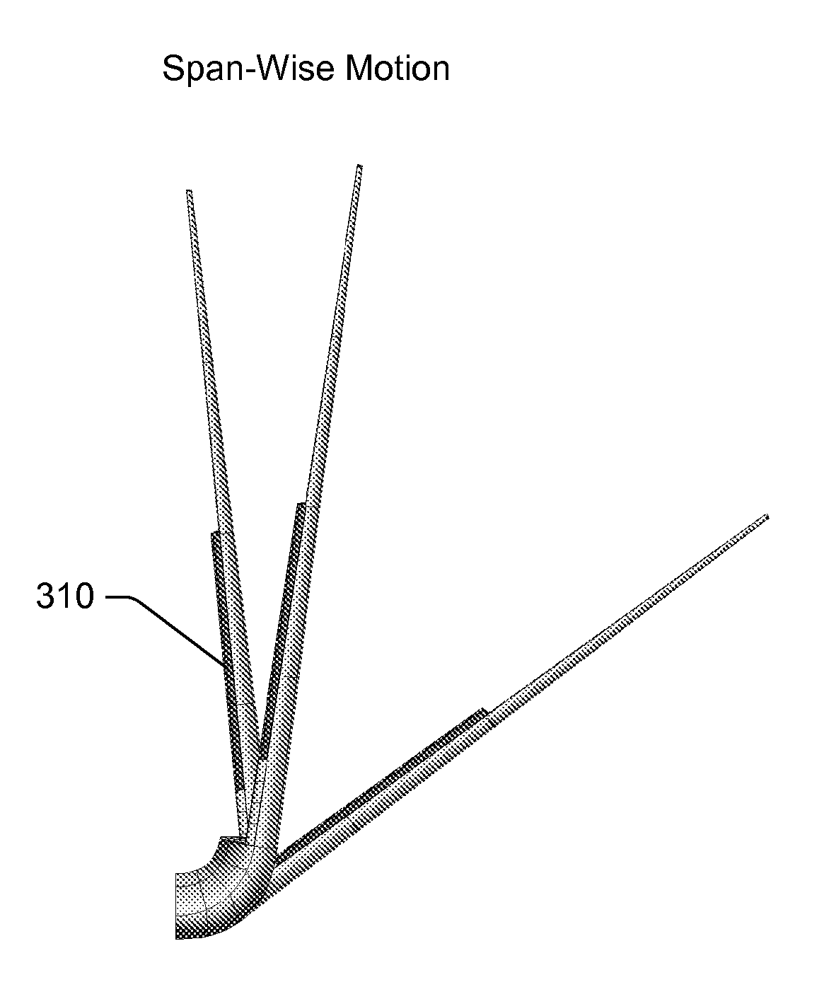
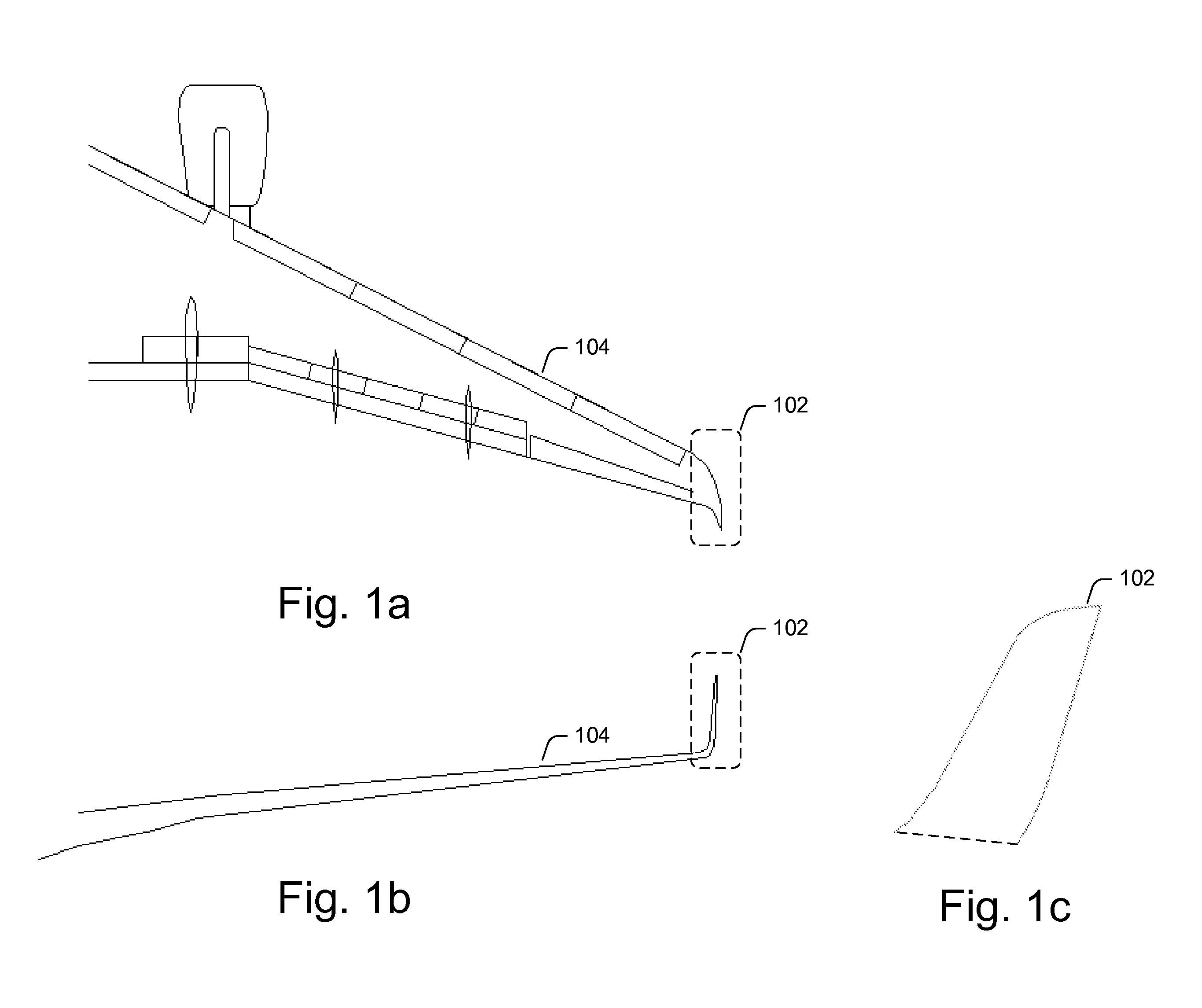
[0005]The present disclosure is directed to systems and methods for providing variable geometry winglets. Variable geometry winglets, as provided by embodiments of systems and methods in accordance with the present disclosure, may advantageously confer fuel efficiency in both cruise and non-cruise conditions. Moreover, these variable geometry winglets may also induce lower wing bending loads than winglets that do not possess variable geometry. Furthermore, certain embodiments of the variable geometry winglets may be reversibly canted inboard to reduce the total wingspan of an aircraft while it is on the ground, thereby enabling the aircraft to meet existing gate clearance requirements while maximizing airborne wingspan during flight.
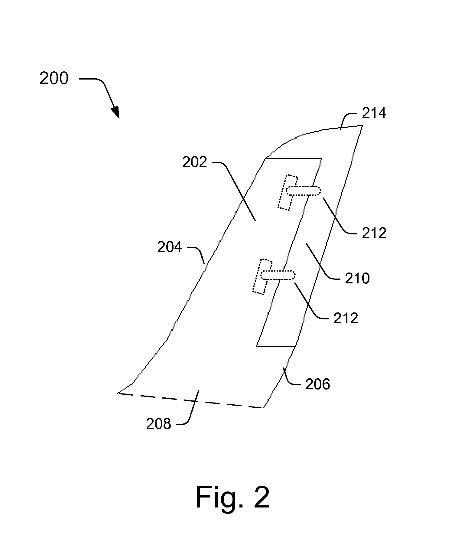
[0007]In another embodiment, a method for adapting an aircraft to a plurality of flight conditions comprises providing a winglet to each wing. The winglet includes a body portion. The body portion includes at least one of a deflectable control surface, a shape memory alloy (SMA) bending plate, and a SMA torque tube. Once the aircraft is moving through the atmosphere, the method further includes providing a winglet modification signal. The winglet is then modified based on the modification signal to at least one of reduce induced drag and redistribute a wing load. In an additional embodiment, a plurality of winglets may be modified asymmetrically to augment either the rolling moment or the yaw moment of the aircraft. In other words, asymmetrical winglet morphing, such as differentially morphing a first winglet and a second winglet, can generate a rolling moment and / or a yawing moment that augment similar moments generated by ailerons, spoilers, and / or rudders.

Problems solved by technology

Moreover, these variable geometry winglets may also induce lower wing bending loads than winglets that do not possess variable geometry.

Method used


Image

  • Controllable winglets
  • Controllable winglets
  • Controllable winglets

Examples


Embodiment Construction

[0018]The present invention relates to systems and methods for providing winglets to enhance aircraft performance. Many specific details of certain embodiments of the invention are set forth in the following description and in FIGS. 1-6 to provide a thorough understanding of such embodiments. The present invention may have additional embodiments, or may be practiced without one or more of the details described below.

[0019]Generally, embodiments of systems and methods in accordance with this disclosure provide variable geometry winglets. These variable geometry winglets are configured to change the conformation of their airflow surfaces in response to different flight conditions. Accordingly, the variable geometry winglets of the present disclosure may maximize fuel efficiency for both cruising and non-cruising flight conditions. Moreover, the variable geometry winglets are also capable of changing their conformation to reduce wing loads, such as wing loads associated with high maneu...


PUM


Abstract

Systems and methods for providing variable geometry winglets to an aircraft are disclosed. In one embodiment, a winglet includes a base portion configured to attach to a wing. The winglet further includes a body portion. In turn, the body portion includes at least one of a deflectable control surface, a shape memory alloy (SMA) bending plate, and a SMA torque tube. The base portion is configured to attach to the wing such that the body portion projects at an upward angle from the wing.

Description

FIELD OF THE INVENTION[0001]This invention relates to systems and methods for providing winglets, and more specifically, to systems and methods for providing winglets to enhance aircraft performance.BACKGROUND OF THE INVENTION[0002]In today's commercial transport industry, it is highly desirable to design aircraft configurations that yield reduced fuel burn per seat-mile, as fuel burn per seat-mile is a metric of fuel efficiency. Efficient aircraft configurations are ever more important as fuel costs continue to increase.[0003]Winglets have been used to reduce aircraft fuel consumption. The winglets may reduce the induced drag of the aircraft and improve the lift-to-drag ratio, thereby improving fuel efficiency. However, previous winglets are typically designed to provide maximum drag reduction and ideal improvement to the lift-to-drag ratio under cruise flight conditions. Consequently, these winglets may not provide optimal fuel efficiency during non-cruise conditions, such as duri...

Claims


Application Information

Patent Timeline
Patent Type & Authority Patents(United States)
IPC IPC(8): B64C23/06
CPCB64C23/065Y02T50/164B64C23/076B64C23/072Y02T50/10
Inventor SANKRITHI, MITHRA M. K. V.FROMMER, JOSHUA B.
Owner THE BOEING CO
Learn More