Diagnostic system and diagnostic method for vehicle

a diagnostic system and vehicle technology, applied in the direction of braking system, vehicle position/course/altitude control, instruments, etc., can solve the problems of not improving fuel efficiency so much, and it is impossible to determine whether the effect of deterioration of fuel efficiency

Inactive Publication Date: 2011-09-29
TOYOTA JIDOSHA KK
View PDF15 Cites 21 Cited by
  • Summary
  • Abstract
  • Description
  • Claims
  • Application Information

AI Technical Summary

Benefits of technology

[0008]The invention provides a diagnostic system and a diagnostic method for a vehicle, which is able to calculate a fuel efficiency that depends on the state of th

Problems solved by technology

In contrast, when the fuel efficiency deteriorates because of the state of the vehicle itself, it is necessary to inspect and maintain the vehicle for improvement in fuel efficiency, and there is a possibility that the fuel efficiency may not be improved so much depe

Method used


Image

  • Diagnostic system and diagnostic method for vehicle
  • Diagnostic system and diagnostic method for vehicle
  • Diagnostic system and diagnostic method for vehicle

Examples


first embodiment

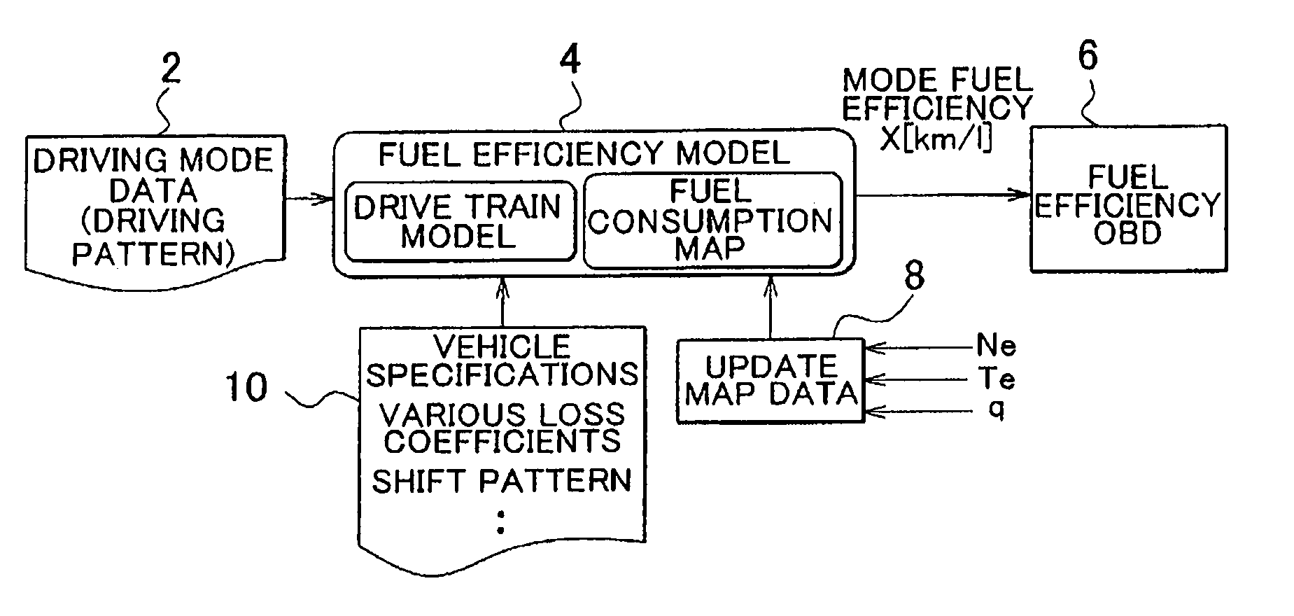
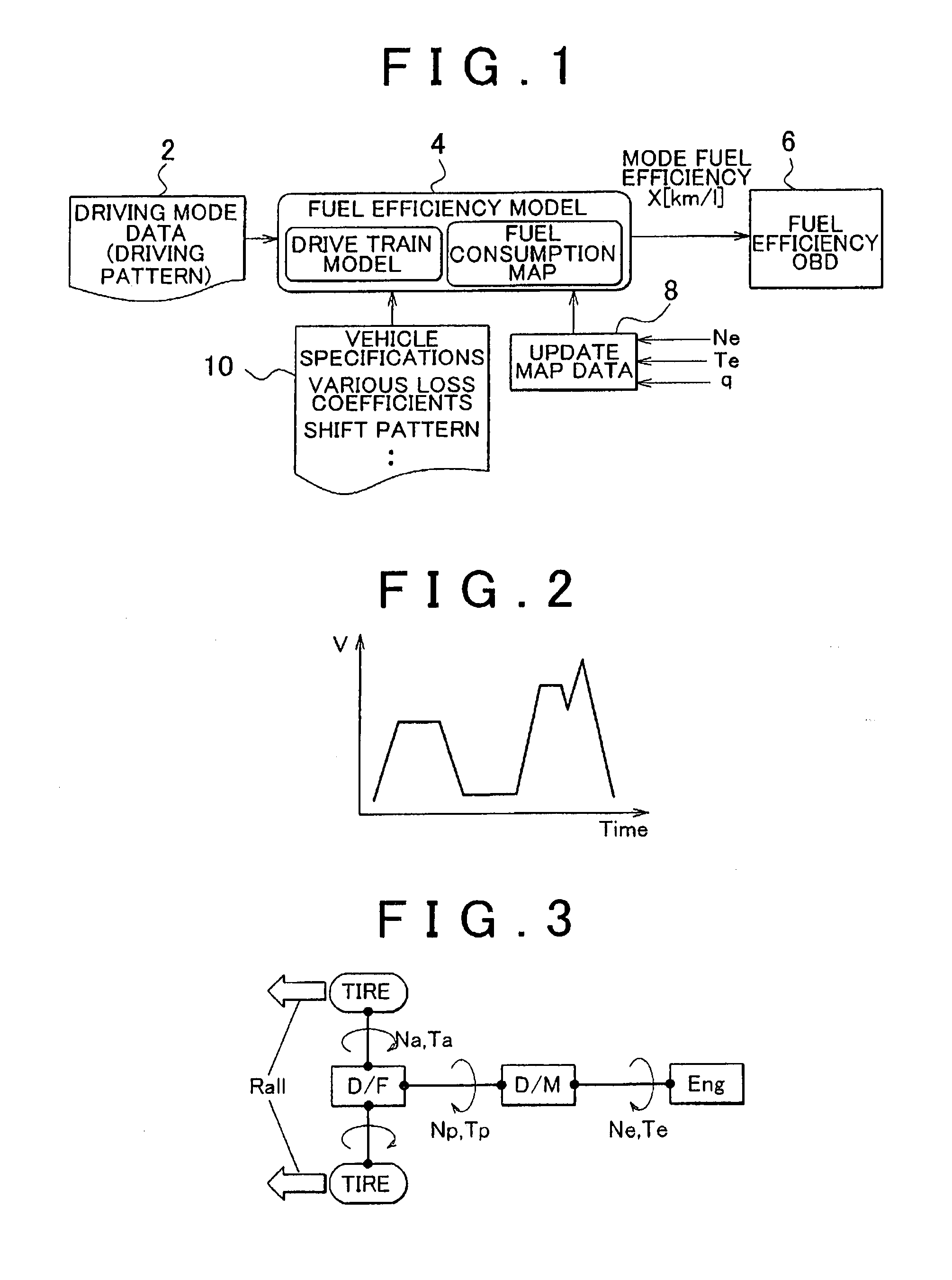
[0049]A vehicle or a diagnostic target in the first embodiment is a vehicle that is driven by an internal combustion engine (hereinafter, simply referred to as engine). The vehicle includes a manual transmission or an electromagnetic clutch-type automatic transmission in a drive train. The type of the engine is not limited. A diagnostic system according to the present embodiment is implemented as one of functions of a controller provided for the vehicle. FIG. 1 shows a block diagram of the configuration of the case where the controller of the vehicle functions as the diagnostic system. The configuration shown in FIG. 1 is virtually implemented in such a manner that a CPU of the controller operates in accordance with a program stored in a memory of the controller.

[0050]As shown in FIG. 1, the diagnostic system is formed of five elements 2, 4, 6, 8 and 10. One of the elements that constitute the diagnostic system is a driving mode data storage unit 2 that stores diagnostic driving mod...

first alternative embodiment

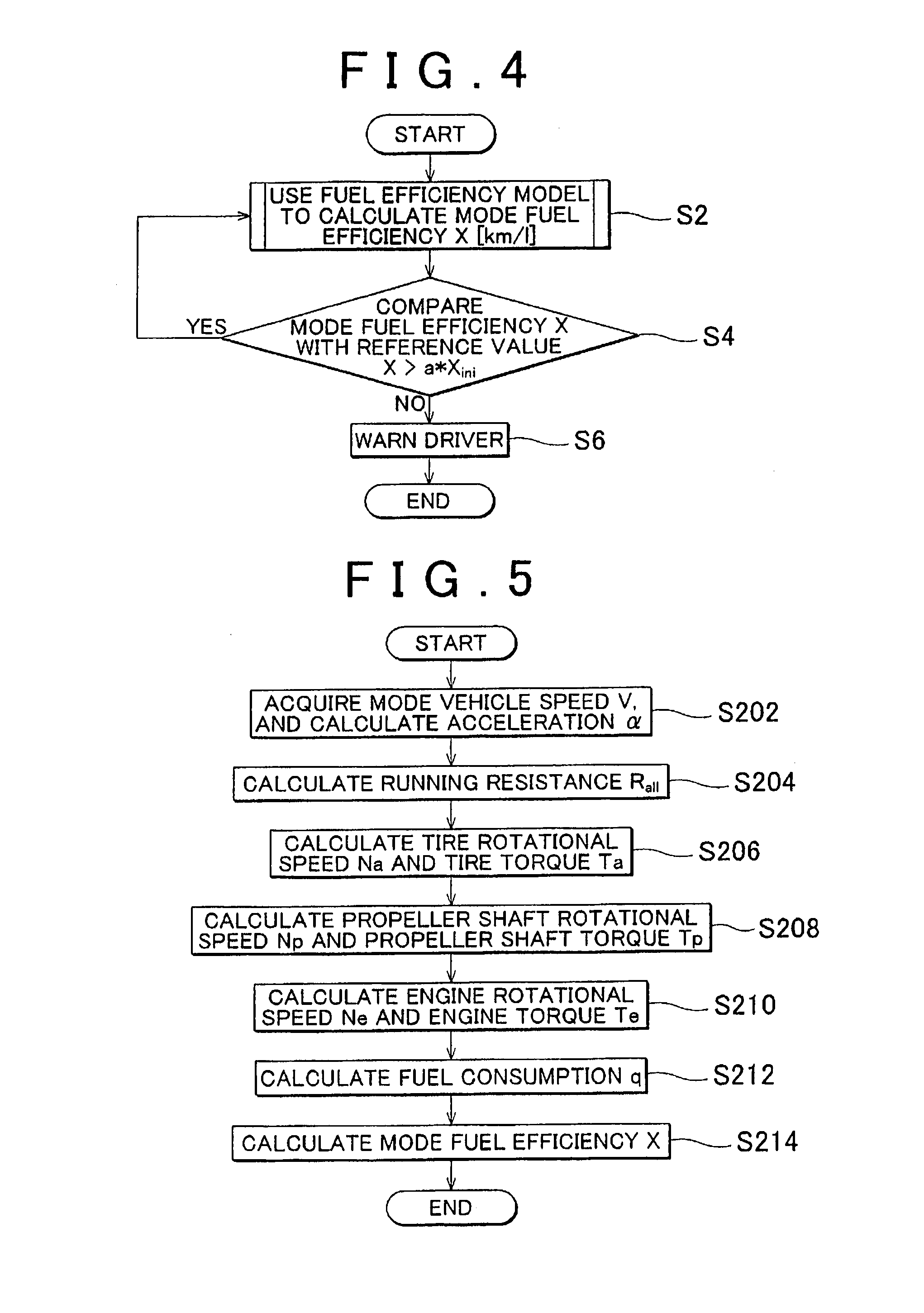
[0071]For example, the aspect of the invention may be applied to a vehicle equipped with a torque converter automatic transmission. In this case, it is only necessary that the process of step S210 in the flowchart shown in FIG. 5 is replaced with the processes of steps S220, S222, S224 and S226 in the flowchart shown in FIG. 6.

[0072]The flowchart of FIG. 6 will be described. In step S220, a torque converter rotational speed Nc and a torque converter torque Tc are calculated on the basis of the propeller shaft rotational speed Np and the propeller shaft torque Tp. A torque converter model that models the transmission characteristic of a torque converter using a physical equation, an empirical formula or a map for the above calculation. In step S222, an engine rotational speed Ne and an engine torque Te are calculated from the torque converter rotational speed Nc and the torque converter torque Tc.

[0073]The gear ratio iM of the transmission is required for calculating the torque conve...

second embodiment

[0075]A vehicle or a diagnostic target in the second embodiment is a vehicle that is driven by an internal combustion engine (hereinafter, simply referred to as engine). The engine equipped for the vehicle is a spark ignition engine of which an air-fuel ratio is controlled to a stoichiometric air-fuel ratio. The other engine specifications are not limited. The diagnostic system according to the second embodiment is implemented as one of functions of a controller provided for the vehicle. FIG. 7 shows a block diagram of the configuration of the case where the controller of the vehicle functions as the diagnostic system. The configuration shown in FIG. 7 is virtually implemented in such a manner that a CPU of the controller operates in accordance with a program stored in a memory of the controller. Hereinafter, like reference numerals denote similar components to those of the first embodiment, and the description that overlaps the first embodiment is omitted.

[0076]FIG. 8 is a conceptu...


PUM


Abstract

A diagnostic system for a vehicle driven by an internal combustion engine acquires a diagnostic driving pattern defined by a vehicle speed; stores a drive train model for calculating a torque and rotational speed of the internal combustion engine backward from a vehicle speed and an acceleration; stores map data in which a fuel consumption is associated with a torque and rotational speed of the internal combustion engine; updates the map data on the basis of a result of actual control over the internal combustion engine; uses the drive train model to calculate changes in torque and rotational speed of the internal combustion engine when the vehicle is caused to drive in accordance with the driving pattern; and uses the calculated changes in torque and rotational speed and the map data to calculate a fuel efficiency when the vehicle is caused to drive in accordance with the driving pattern.

Description

BACKGROUND OF THE INVENTION[0001]1. Field of the Invention[0002]The invention relates to a diagnostic system and a diagnostic method for a vehicle that is driven by an internal combustion engine and, more particularly, to a system and a method that diagnoses the fuel efficiency of a vehicle.[0003]2. Description of the Related Art[0004]Various methods of calculating the fuel efficiency (that is, the relationship between a fuel consumption and a mileage) of a vehicle, particularly, a vehicle driven by an internal combustion engine, are suggested in Japanese Patent Application Publication No. 2006-183506 (JP-A-2006-183506), Japanese Patent Application Publication No. 2004-60548 (JP-A-2004-60548), Japanese Patent Application Publication No. 2006-118480 (JP-A-2006-118480), Japanese Patent Application Publication No. 1-290967 (JP-A-1-290967), and the like. For example, JP-A-2006-183506 describes a method of calculating the fuel efficiency on the basis of a fuel injection amount and a torq...

Claims


Application Information

Patent Timeline
IPC IPC(8): G06F7/00
CPCB60R16/0236B60R16/0232Y02T10/84
Inventor SANO, TOMOYAUEDA, KOICHI
Owner TOYOTA JIDOSHA KK
Why Eureka
Try Eureka