
Ring generator

a generator and ring technology, applied in the direction of electric generator control, machines/engines, surveillance and security operations, etc., can solve the problems of many challenging constraints in designing appropriate systems for such applications, and the effort has failed to provide a satisfactory solution for multiple constraints, so as to achieve low visibility, high thrust to weight ratio, and high power to weight ratio

Inactive Publication Date: 2010-06-01
ADVANCED PROPULSION TECH
View PDF130 Cites 21 Cited by
  • Summary
  • Abstract
  • Description
  • Claims
  • Application Information

AI Technical Summary

Benefits of technology

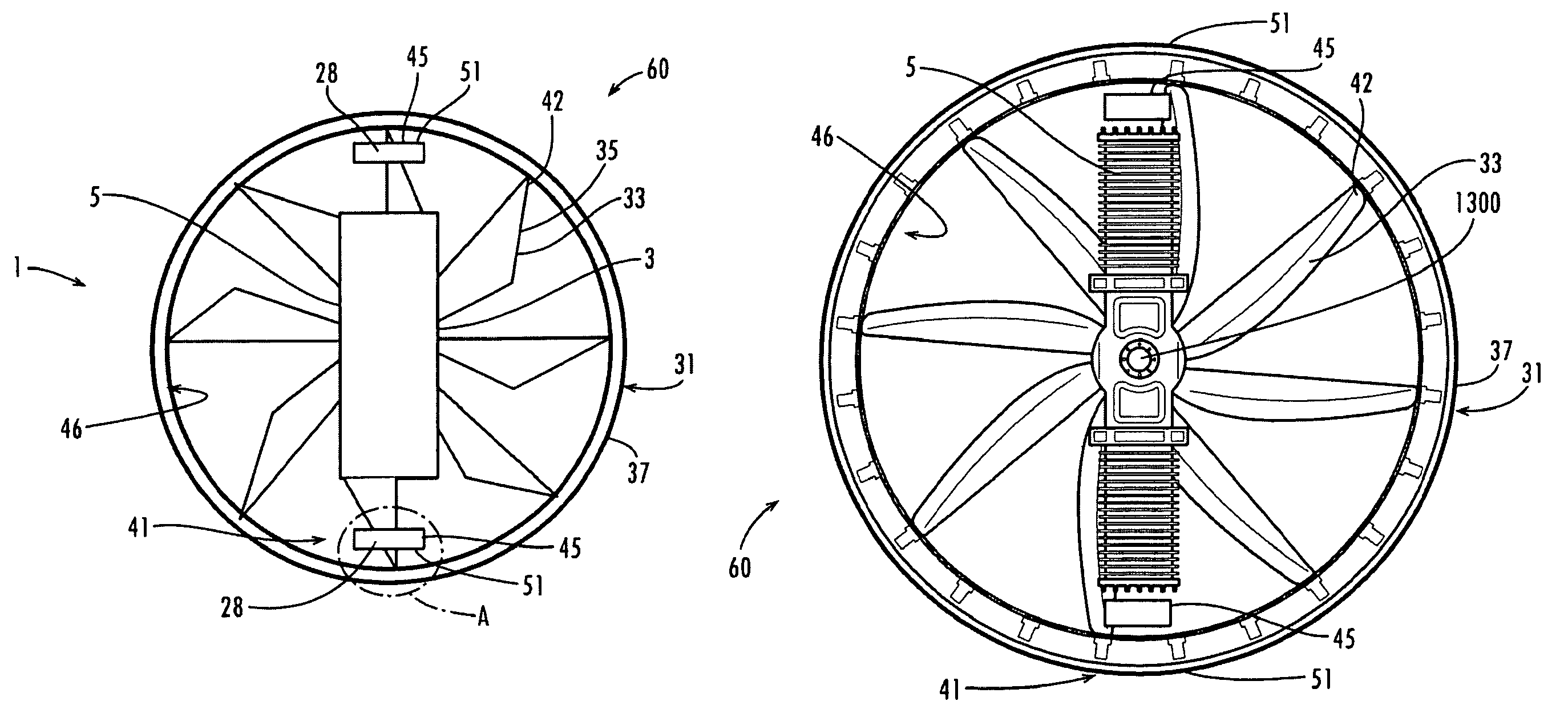
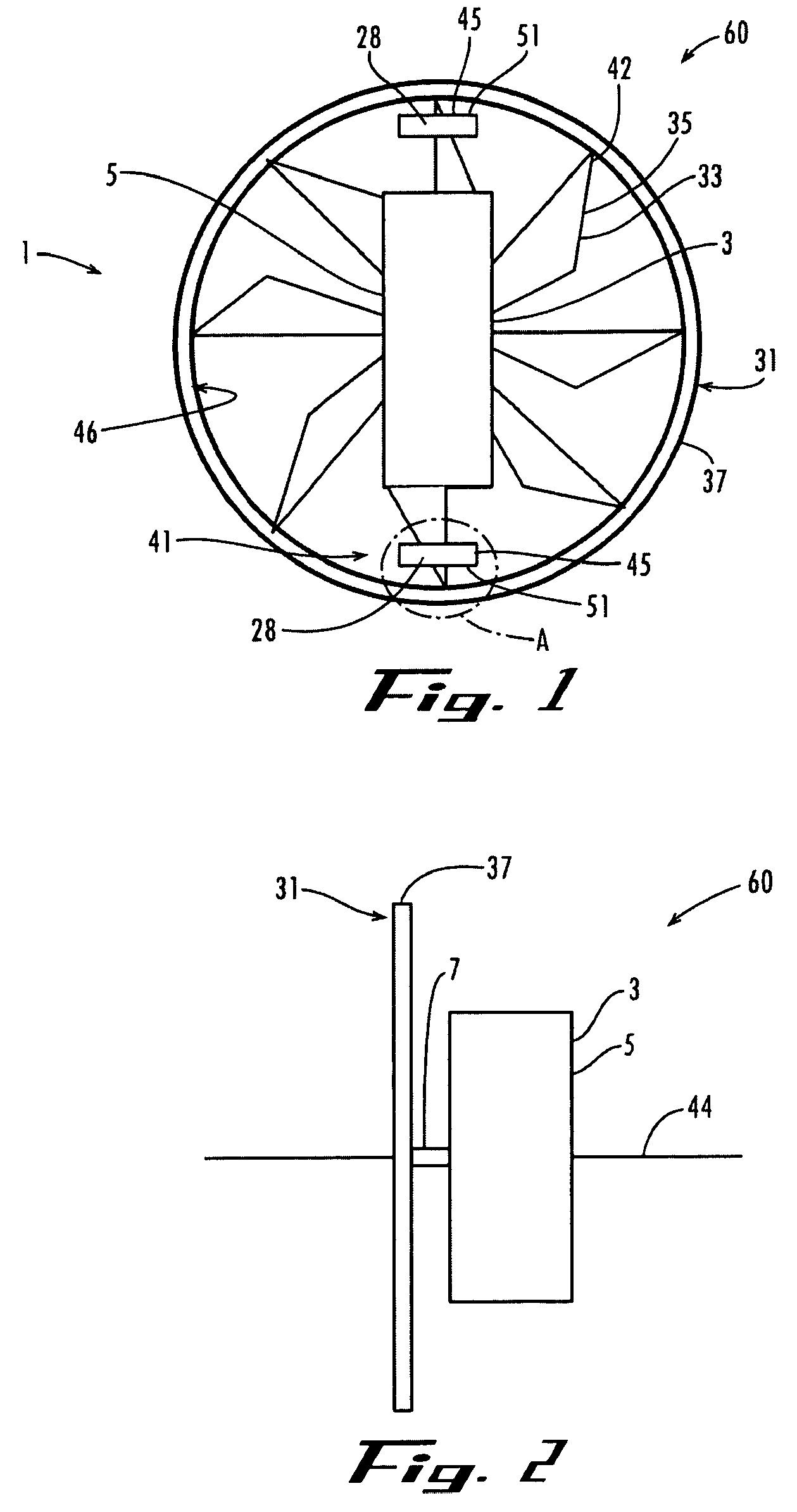
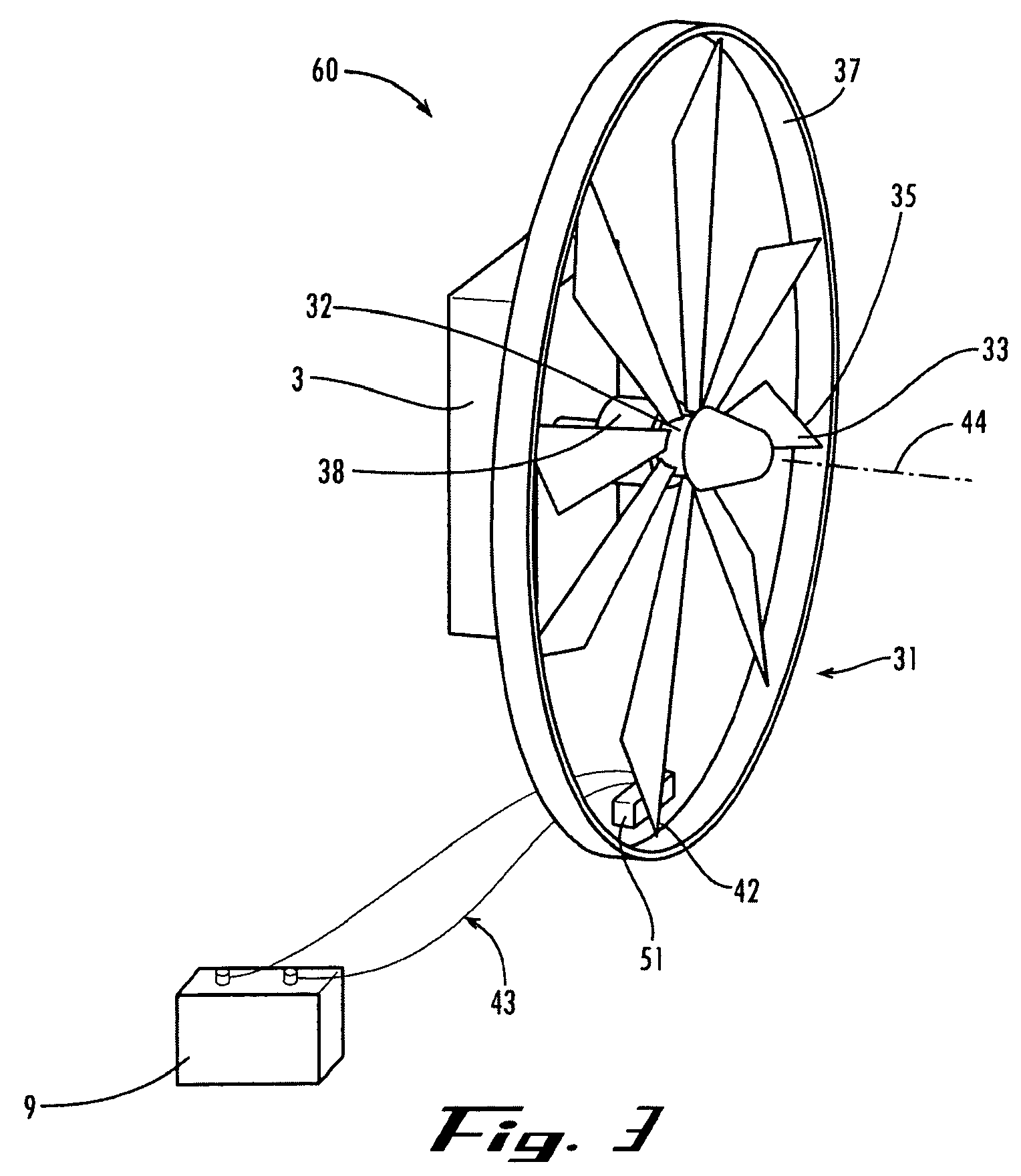
"The present invention provides an aerial vehicle with a power generating device that has minimal visibility, high power to weight ratio, high thrust to weight ratio, low noise production, low vibration, fuel efficiency, long flight times, and mechanical simplicity for serviceability in the field. The power generating device includes a ring assembly with blades connected to a common hub, and a magnetic flux generating mechanism and a current conducting element that induce electric current when there is relative movement between them. The power generating device can be used in an opposed piston, opposed cylinder engine, or a rotating hub with magnetic flux generating elements and current conducting elements."

Problems solved by technology

Unmanned Aerial Vehicles (UAVs) and Organic Aerial Vehicles (OAVs) used in military, law enforcement, surveillance and security operations present particularly challenging requirements for power, weight, fuel consumption, vibration, starting and electrical generation.
Designing appropriate systems for such applications are subject to many challenging constraints.
Unfortunately, while existing efforts might satisfactorily address any given constraint, those efforts have failed to provide a satisfactory solution for multiple constraints.
Providing an inventory of engines of various sizes and capacities is prohibitive.

Method used


Image

  • Ring generator
  • Ring generator
  • Ring generator

Examples


Embodiment Construction

[0029]In the following detailed description, reference is made to the accompanying drawings which form a part hereof wherein like numerals designate like parts throughout, and in which is shown by way of illustration specific embodiments in which the invention may be practiced. It is to be understood that other embodiments may be utilized and structural or logical changes may be made without departing from the scope of the present invention. Therefore, the following detailed description is not to be taken in a limiting sense, and the scope of the present invention is defined by the appended claims and their equivalents.

[0030]The present invention is directed towards power generating systems. In accordance with the present invention, an embodiment of a power generating system comprises a current generating device powered by a two stroke, opposed piston opposed cylinder (OPOC) internal combustion engine. Embodiments of the present invention are particularly suitable to provide thrust ...


PUM


Abstract

The present invention is a rotary device that may be adapted for use as a propeller assembly and electrical generator for aerial vehicles or other vehicles intended for fluid media. In one example, the device includes a ring assembly having a plurality of centrally linked blades coupled to a rotatable common hub. Rotary motion of the ring assembly is facilitated by coupling it to an opposed cylinder, opposed piston, internal combustion. The ring assembly includes components of an electrical power generating system so that electrical power is produced from the rotation of the ring assembly.

Description

RELATED APPLICATION[0001]This application claims priority from U.S. Provisional Application Ser. No. 60 / 482,848, filed Jun. 25, 2003, the contents of which are hereby incorporated by reference as if recited in full herein for all purposes.GOVERNMENT FUNDING[0002]The U.S. Government has a paid-up license for certain inventions claimed in this document and the right in limited circumstances to require the patent owner to license others on reasonable terms, as provided for by the terms of Contract No. DAAH01-03-C-R077 awarded by U.S. Army Aviation and Missile Command.FIELD OF INVENTION[0003]The present invention relates generally to electric power generators, and more specifically to an electric power generator powered by a two-stroke internal combustion engine having a pair of opposed cylinders, each cylinder having a pair of opposed pistons.BACKGROUND OF THE INVENTION[0004]Unmanned Aerial Vehicles (UAVs) and Organic Aerial Vehicles (OAVs) used in military, law enforcement, surveillan...

Claims


Application Information

Patent Timeline
Patent Type & Authority Patents(United States)
IPC IPC(8): F02B63/04F03D9/00H02P9/04B64C39/02
CPCB64C39/024F02B75/24H02K7/183H02K7/1884F02B61/04B64C2201/042B64C2201/044B64C2201/162Y02E10/725F03G7/08Y02E10/72B64U50/11B64U50/19B64U50/14B64U30/26
Inventor HOFBAUER, PETERMCCLEER, PATRICK
Owner ADVANCED PROPULSION TECH
Learn More