One camera club monitor

a technology of club monitor and camera, which is applied in the field of striking instrument and striking object monitoring system, can solve the problem that there is no satisfactory system for accurately sensing the movement of the golf club head using a single camera, and the proposal of a single camera is not satisfactory

Active Publication Date: 2010-06-29
ACUSHNET CO
View PDF58 Cites 29 Cited by
  • Summary
  • Abstract
  • Description
  • Claims
  • Application Information

AI Technical Summary

Benefits of technology

[0013]As described in greater detail below, the present invention is capable of accurately measuring the striking instrument and object. For instance, in one embodiment the accuracy of the system or of the image analyzer for determining the golf ball impact location is within 0.25 inch. In another embodiment, the accuracy of the system or of the image analyzer for determining the golf ball impact location is within 0.10 inch. In yet another embodiment, the accuracy of the system or of the image analyzer for determining the golf ball impact location is comparable to the accuracy of a 2-camera system.
[0016]A triggering unit may be used with the present invention. One advantage of providing a triggering unit is that it may be useful for determining when the single camera captures an image of the striking instrument and object. In one embodiment, the triggering unit comprises a light source, a reflector, and an optical sensor. In another embodiment, the triggering system comprises an ultrasonic emitter and receiver.

Problems solved by technology

To date, however, no satisfactory system for accurately sensing golf club head movement using a single camera has yet been proposed.

Method used


Image

  • One camera club monitor
  • One camera club monitor
  • One camera club monitor

Examples


example 1

[0110]A driver club was marked with four orange fluorescent circular markers. Two markers were placed on the toe separated by 0.96 inches and two markers placed on the shaft were separated by 1.51 inches. The club markers were then calibrated using a two-camera system as well as a one-camera system using the calibration steps described herein.

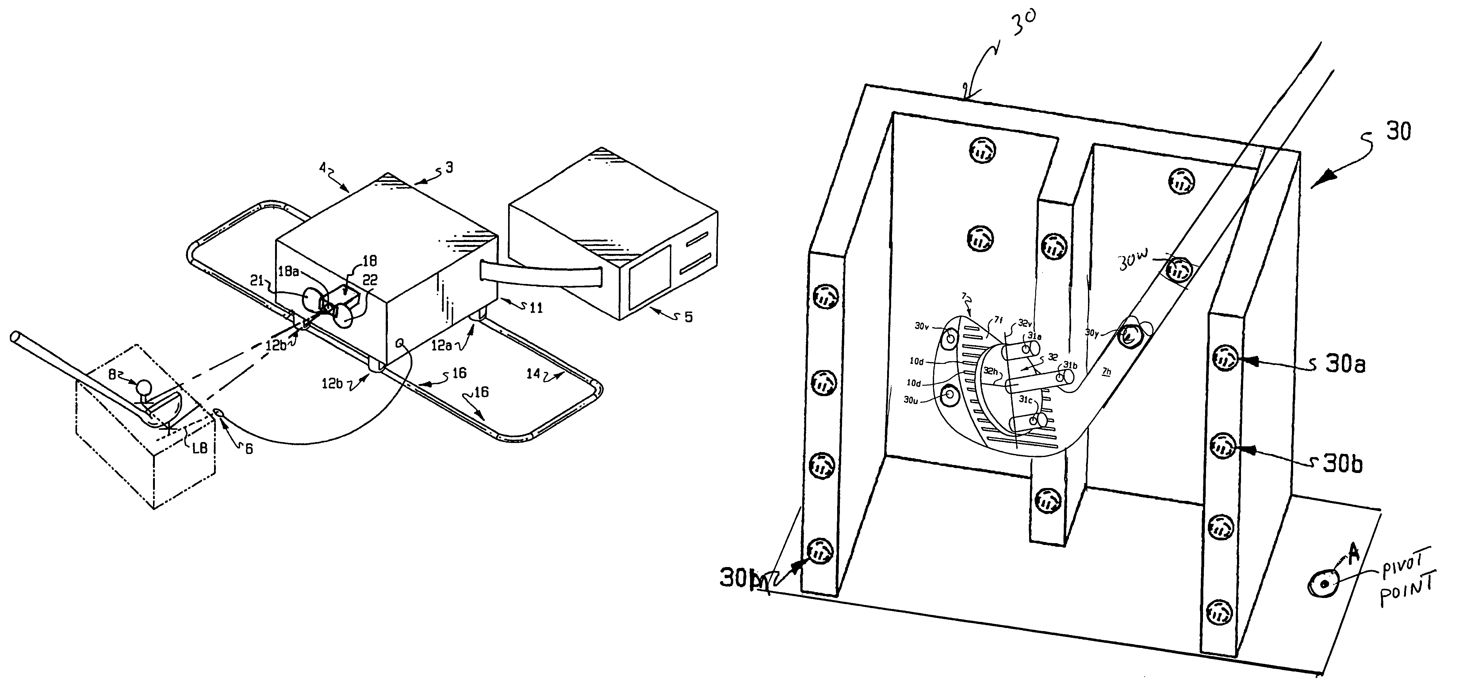
[0111]Six golf swings were analyzed with the calibrated club and measurements were made with the two cameras separated in the vertical direction. The cameras were separated vertically in height by about seven inches. The two cameras were focused at a distance of 25 inches from the field of view of the swing area. Both were Sony XCD-X700 cameras with 16 mm focal length lenses and orange 600 nm wavelength filters of 10 nm bandwidth. The average result of the six swings and the standard deviation are listed below computed from the bottom camera and top camera.

[0112]The results of the triangulation method described in a previous patent (U.S. Pat. N...

example 2

[0114]A five iron club was marked with for orange fluorescent circular markers. Two markers were placed near the toe separated by 1.1 inches and two markers on the shaft were separated by 3.2 inches. The club marker positions were then calibrated. Six golf swings were taken with this calibrated club and measured using the three camera systems described above and used in Example 1.

[0115]The average results listed below are measurements computed from the bottom camera and top camera operating together as a two camera system and operating independently of each other as one camera systems. The results of the triangulation method for a two camera system described in a previous patent (U.S. Pat. No. 5,575,719 to Gobush et al.) is listed in the bottom row. As can be seen from the results shown in Table 3, the two computations with one camera once again is equivalent in accuracy and precision to the two camera system method.

[0116]

TABLE 3faceX impactY impactspeedpathattackdroop angleloft ang...


PUM


Abstract

This application relates to a single camera monitoring system useful for determining parameters relating to a striking instrument as it approaches an object. The monitoring system may be used to determine the swing characteristics of a golf club as it approaches and impacts with a golf ball. The accuracy of the single camera system may be comparable to the accuracy of more complex, multi-camera systems. The application also relates to methods for calibrating a single camera system.

Description

FIELD OF THE INVENTION[0001]The present invention relates to a striking instrument and struck object monitoring system including one shutterable camera unit, which observes a field of view of which the camera receives light patterns from a plurality of contrasting areas on the instrument and the object in rapid successive sequence. A computer receives the signals generated by the light patterns as received by the camera and discriminates between the signals to determine the instrument's movement and orientation, as well as the conditions at impact with the object.BACKGROUND OF THE INVENTION[0002]In general, devices for measuring golf ball flight characteristics are well known. In addition, techniques of detecting golf clubhead position and golf ball position shortly after impact using photoelectric means to trigger a flash to permit a photograph to be taken of the clubhead have been disclosed. Golf ball or golf clubhead movement has been determined by placing reflective areas on a b...

Claims


Application Information

Patent Timeline
Patent Type & Authority Patents(United States)
IPC IPC(8): A63B69/36A63B57/00A63B69/00
CPCA63B24/0003A63B24/0021A63B69/3658A63B2220/807A63B2024/0031A63B2220/05
Inventor GOBUSH, WILLIAM
Owner ACUSHNET CO
Why Eureka
Try Eureka