
Wheelbarrow stabilizer with improved load distribution

a technology of stabilizer and wheelbarrow, which is applied in the direction of loading-carrying vehicle superstructure, understructure, hand cart, etc., can solve the problems of no practical, simple, functional wheelbarrow stabilizer known, and the basic geometry is not practical, so as to achieve better stability and improve the effect of load distribution

Active Publication Date: 2010-07-06
TRUPER HERRAMIENTAS DE C V
View PDF24 Cites 19 Cited by
  • Summary
  • Abstract
  • Description
  • Claims
  • Application Information

AI Technical Summary

Benefits of technology

"The present invention is a wheelbarrow stabilizer that improves load distribution and stability under loaded conditions. It supports repeated, alternating, and fluctuating loads without losing its basic geometry. It also improves stability on uneven ground and reinforces the lateral support (leg). The stabilizer is made of a monolithic angled piece made up of two arms that define a triangular shape, with supporting points on the ground and a straight arm that acts as a support. The arched area absorbs deformations and cushions the load applied to the element, making a stabilizer for each leg necessary. The stabilizer is made of fluted sections of steel or a strip of shaped steel, extruded and perforated on the ends. It is designed to improve the wheelbarrow's stability and performance."

Problems solved by technology

The supports and stabilizers found in the market work best on flat surfaces, and with time lose their basic geometry, upon supporting repeated, alternating and fluctuating loads and due to work on uneven surfaces.
Up to now no practical, simple, functional wheelbarrow stabilizer known compares to the state of the art stabilizers and supports which have a shock absorber section that avoids permanent deforming of the element.

Method used


Image

  • Wheelbarrow stabilizer with improved load distribution
  • Wheelbarrow stabilizer with improved load distribution
  • Wheelbarrow stabilizer with improved load distribution

Examples


Embodiment Construction

[0037]The details which characterize the wheelbarrow stabilizer with improved load distribution are clearly shown in the following description and the illustrative drawings which accompany it, the same reference signs designating the same parts.

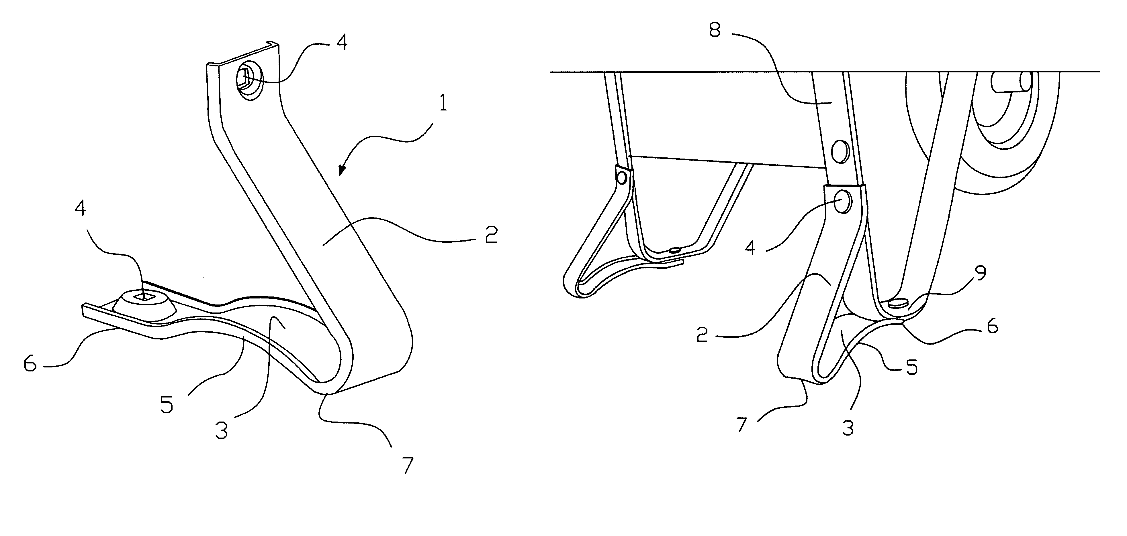
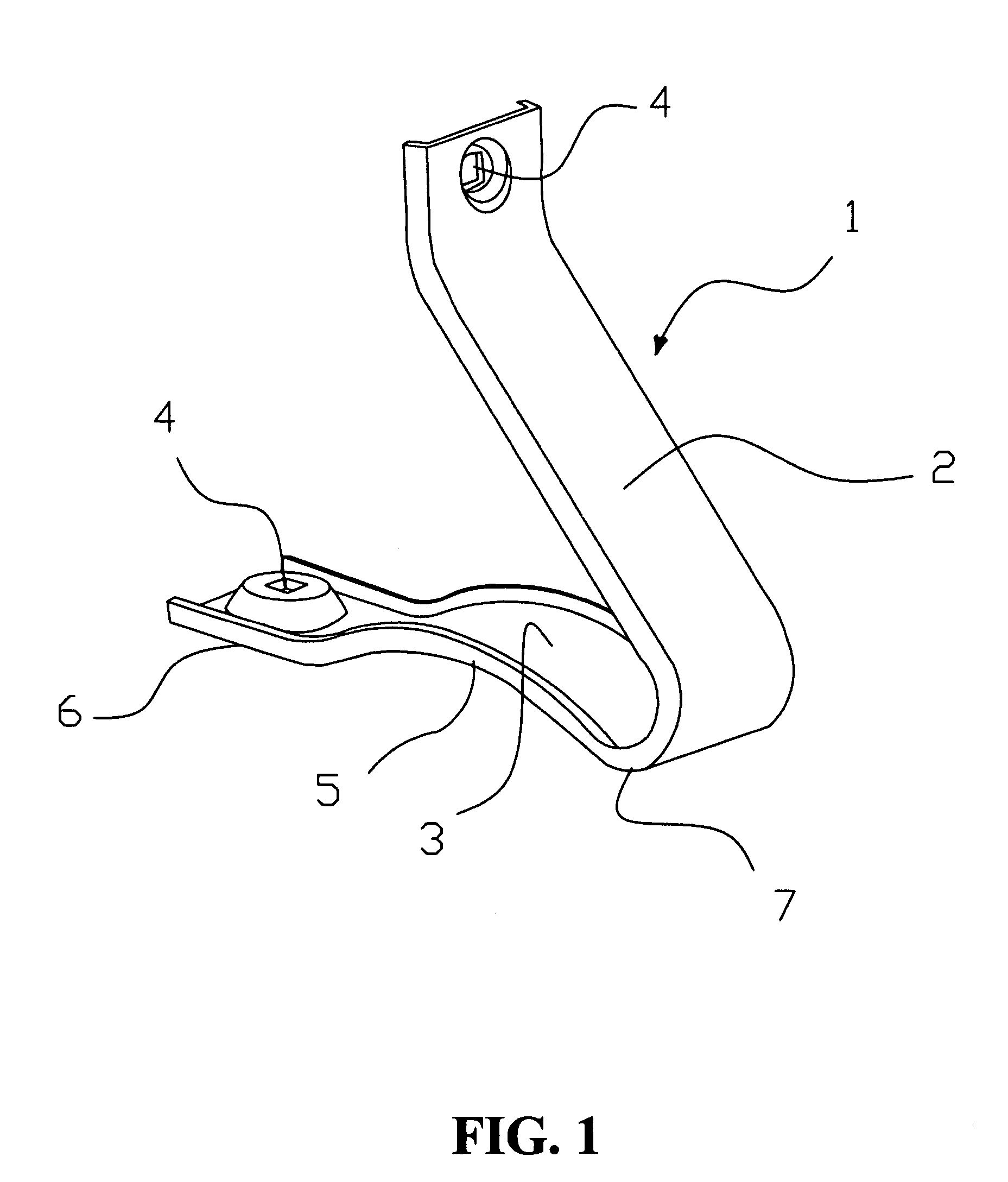
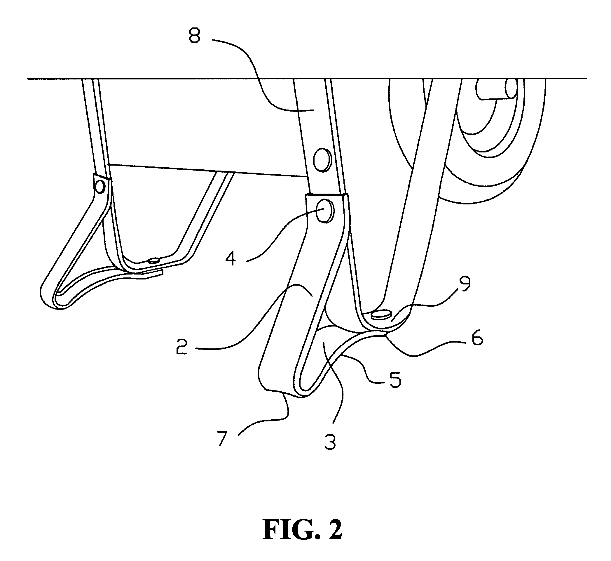
[0038]FIGS. 1 and 2 show, in a conventional perspective view, a wheelbarrow stabilizer with improved load distribution of the present invention and a conventional view of a portion of a wheelbarrow with the stabilizers of the present invention installed, respectively. In the figures, it can be observed that the stabilizer consists of a monolithic piece 1 comprising two arms 2, 3 which form a triangular configuration. Both arms 2 and 3 at the ends have holes 4, preferably square in shape in order to facilitate the insertion of affixing means (not shown) in order to affix to the legs of a wheelbarrow and hide the affixing means. The holes 4 in this shape also make it impossible for the affixing means to rotate on their axis during assembly and ...


PUM


Abstract

A device for stabilizing and supporting wheelbarrows which maintains the balance and increases the resistance of a system (wheelbarrow) including an angled monolithic body which is made up of two arms which define a triangular shape, whose ends have holes for the insertion of affixing means to affix to the leg of a wheelbarrow. In one embodiment, one of said arms makes up an arched area along most of its length which generates two points of support, a first point of support defined on the end of the joint affixing with the leg of the wheelbarrow and a second point of support defined in the area near where the two arms meet to define that angle. The arched area of the arm, positioned substantially horizontally and defining the two points of support, absorbs deformation, and also absorbs the load applied to the element, bringing more stability to the wheelbarrow on flat or irregular surfaces, providing a stabilizer comprised by each leg.

Description

BACKGROUND OF THE INVENTION[0001]1. Field of the Invention[0002]The present invention relates generally to means and devices used to stabilize and support wheelbarrows and more specifically relates to a wheelbarrow stabilizer with improved load distribution which serves to maintain balance and improve the resistance of a system for a wheelbarrow.[0003]2. Background Art[0004]Nowadays many different stabilizing and supporting elements exist which help maintain the balance and / or improve resistance in wheelbarrows, the elements vary in geometry as well as in various types of materials which go from metal bars and pipes to preformed profiles.[0005]Stabilizers are mainly placed as reinforcements in lateral supports (legs): they are usually totally straight in the lower section, which rests on the ground.[0006]The supports and stabilizers found in the market work best on flat surfaces, and with time lose their basic geometry, upon supporting repeated, alternating and fluctuating loads and...

Claims


Application Information

Patent Timeline
Patent Type & Authority Patents(United States)
IPC IPC(8): B62B1/26
CPCB62B1/20B62B5/00B62B2301/00
Inventor ITURBIDE JIMENEZ, SALVADOR
Owner TRUPER HERRAMIENTAS DE C V
Learn More