Device, method and program product for data transmission management
- Summary
- Abstract
- Description
- Claims
- Application Information
AI Technical Summary
Benefits of technology
Problems solved by technology
Method used
Image

Examples
first embodiment
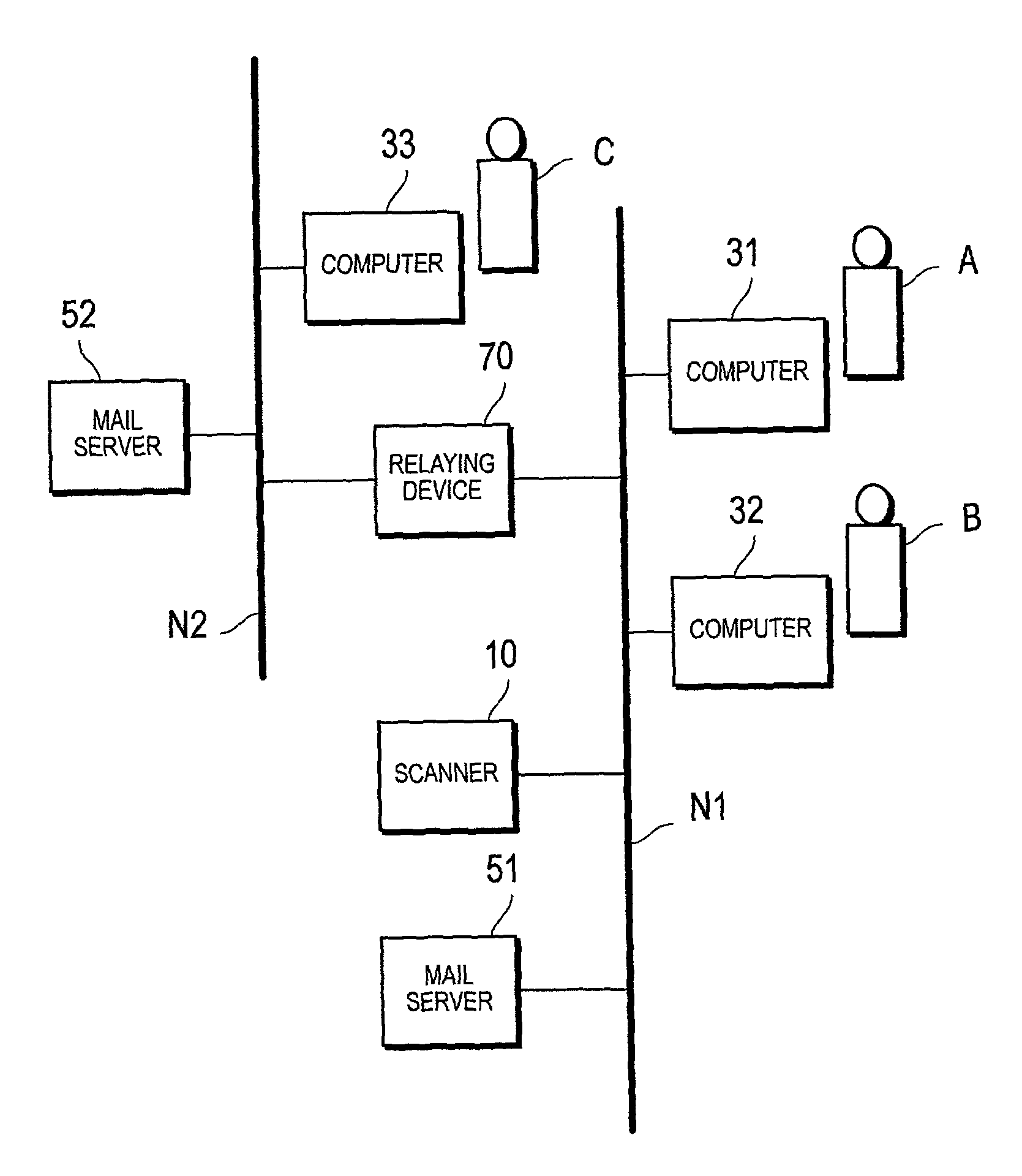
[0033]FIG. 1 is a diagram showing an example of a data transmission system including a data transmission management device according to the present invention.
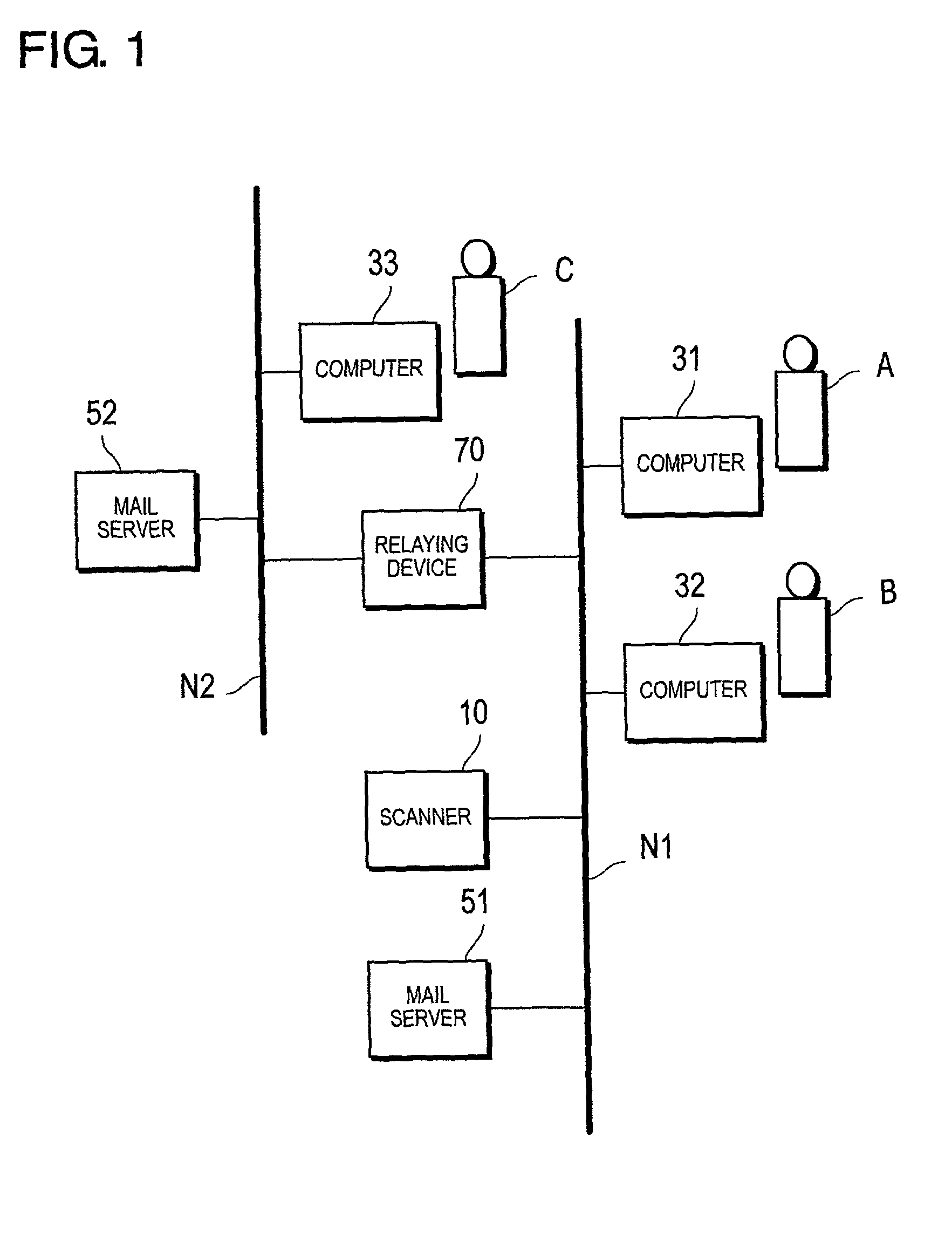
[0034]The data transmission system shown in FIG. 1 includes a scanner 10, which functions as a data transmission device, personal computers (hereinafter simply called “computers”) 31 through 33, mail servers 51 and 52, and a relaying device 70.
[0035]The scanner 10, the computers 31 and 32, and the mail server 51 are connected to the first network N1, while the computer 33 and the mail server 52 are connected to the second network N2. The relaying device 70 connects the first network N1 and the second network N2 to each other. The user of the computer 31 is A, the user of the computer 32 is B, and the user of the computer 33 is C.
[0036]The scanner 10, the computers 31 through 33, and the mail servers 51 and 52 are provided in such a way as to be able to communicate with each other via the networks N1 and N2 as well as the relayi...
second embodiment
[0087]FIG. 14 is a flowchart showing the operation of a mail server capable of functioning as a data transmission management device concerning the present invention. The flowchart shown in FIG. 14 may be stored in the memory unit 62 of the mail server 51 as a control program and may be executed by the control unit 61.
[0088]The second embodiment of the invention is different in that its mail server 51 is capable of functioning as a data transmission management device, described above in relation to the first embodiment, in which its scanner 10 is capable of functioning as the data transmission management device. Mainly the differences between the first and second embodiments will be described and the commonality will be omitted in the following.
[0089]The second embodiment of the invention will be described by referencing the transmission of an e-mail with an attached file from user A to user B or user C.
[0090]As shown in FIG. 14, an e-mail with an attached file is received from user ...
third embodiment
[0105]FIG. 15 is a flowchart showing the operation of a relaying device that is capable of functioning as a data transmission management device according to the invention. The flowchart shown in FIG. 15 may be stored in the memory 82 of the relaying device 70 as a control program and may be executed by the control unit 81.
[0106]The third embodiment is different from the first embodiment in that the relaying device 70 is capable of functioning as a data transmission management device in the former, while the scanner 10 functions as a data transmission management device in the latter. For the most part, the differences between the first and third embodiments will be described and the commonality will be omitted in the following.
[0107]A case of sending a file from user A to user B or to user C will be described. The file transmission is executed according to the specified transfer protocol such as FTP (file transfer protocol).
[0108]As shown in FIG. 15, the file is received from user A ...
PUM
 Abstract
Description
Claims
Application Information
 - R&D Engineer
- R&D Manager
- IP Professional
- Industry Leading Data Capabilities
- Powerful AI technology
- Patent DNA Extraction
Browse by: Latest US Patents, China's latest patents, Technical Efficacy Thesaurus, Application Domain, Technology Topic.
© 2024 PatSnap. All rights reserved.Legal|Privacy policy|Modern Slavery Act Transparency Statement|Sitemap