
Reinforced and bolted rack truss

a rack truss and bolt technology, applied in the direction of girders, dismountable cabinets, furniture parts, etc., can solve the problems of occupying more space, difficult to paint, and difficult to handle the rack truss

Inactive Publication Date: 2010-07-13
KONSTANT PRODS
View PDF56 Cites 25 Cited by
  • Summary
  • Abstract
  • Description
  • Claims
  • Application Information

AI Technical Summary

Benefits of technology

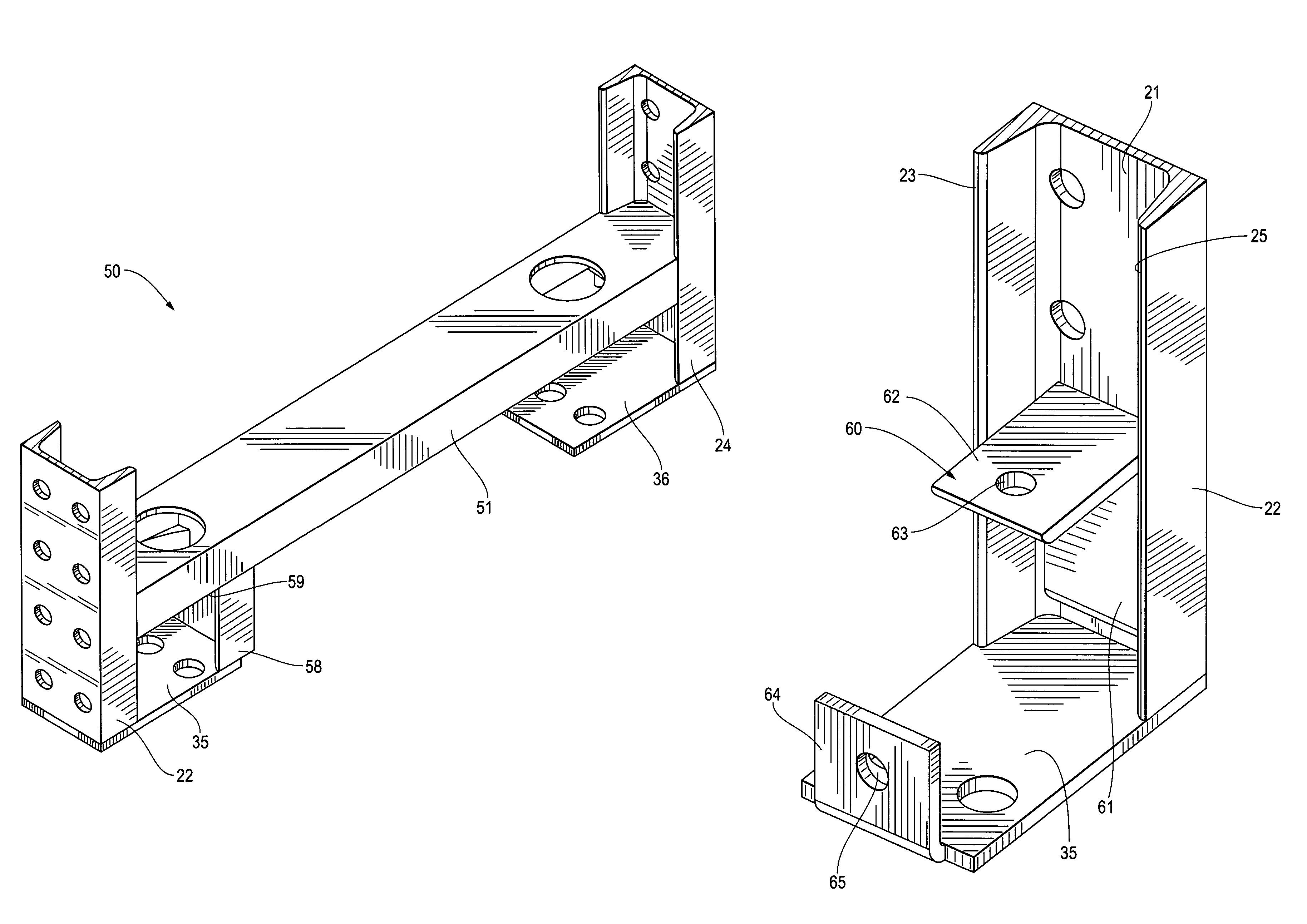
[0006]The present inventions preserve the advantages of known storage racks and storage rack trusses and also provide new features and advantages. For example, the present inventions provide storage racks and rack trusses that may be bolted together at the site making shipping and assembly more efficient and / or which provide reinforcement in the lower portion of the truss to resist abuse from forks of fork trucks and the like.
[0015]A further object of the present inventions is to provide a rack truss that is easy to fabricate, paint, ship, assemble and install.INVENTOR'S DEFINITION OF THE TERMS

Problems solved by technology

Because the trusses are fabricated prior to shipping and installation, known rack trusses are somewhat difficult to handle during assembly, take-up more space during shipping and can be difficult to paint.
This can result in, among other things, a weakened rack structure.

Method used


Image

  • Reinforced and bolted rack truss
  • Reinforced and bolted rack truss
  • Reinforced and bolted rack truss

Examples


Embodiment Construction

[0029]Set forth below is a description of what is currently believed to be the preferred embodiments or best representative examples of the inventions claimed. Future and present alternatives and modifications to the embodiments and preferred embodiments are contemplated. Any alternatives or modifications which make insubstantial changes in function, purpose, structure or result are intended to be covered by the claims of this patent.

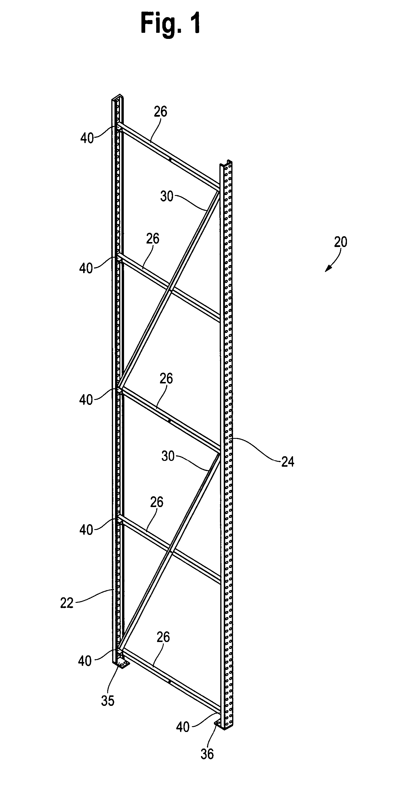
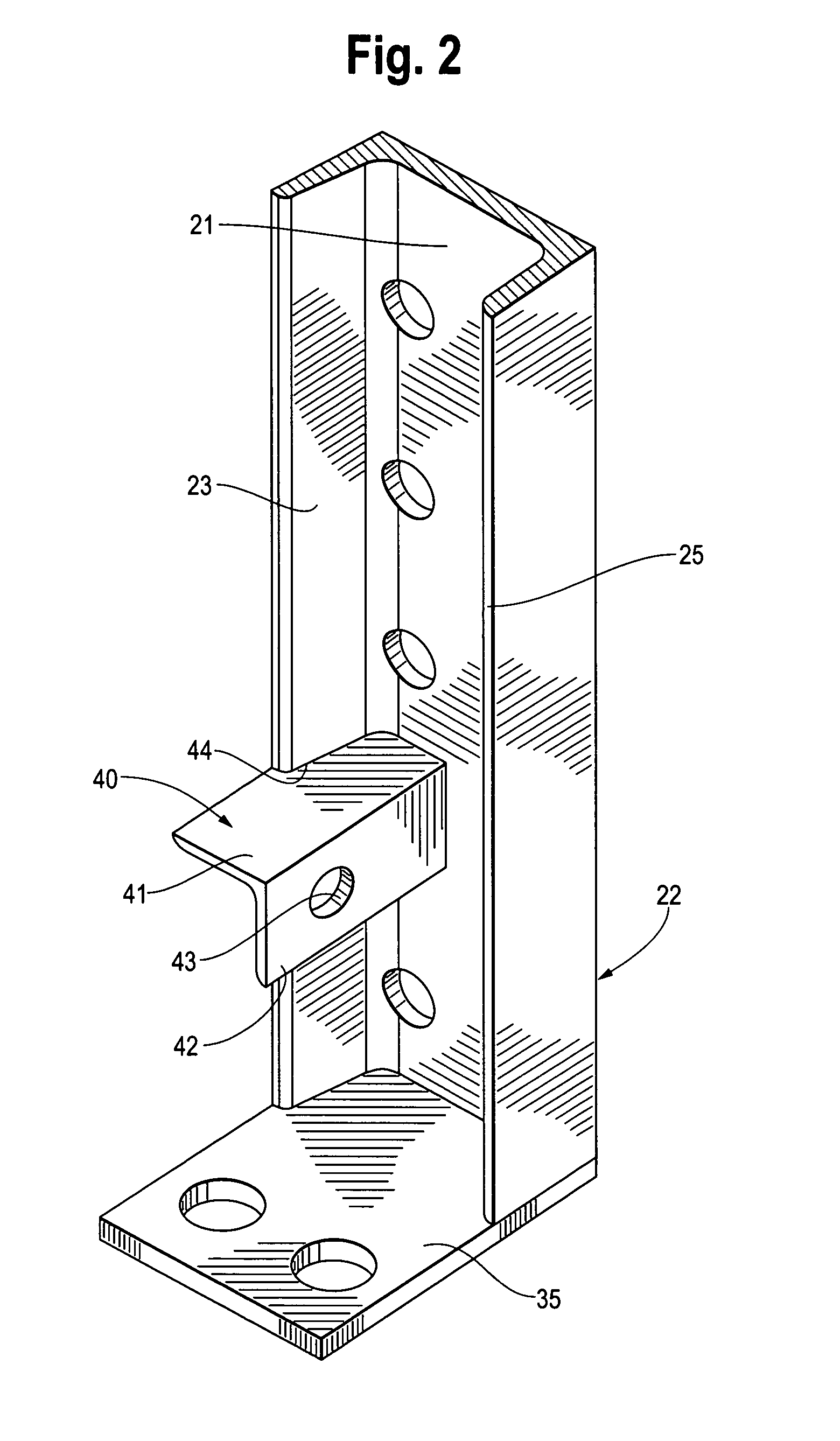
[0030]A preferred embodiment of the bolted truss of the present inventions is shown generally as 20 in FIG. 1. The preferred components of preferred truss 20 are shown in FIGS. 1-6 and 11. A preferred embodiment of the lower truss reinforcement of a bolted truss 20 is shown generally as 50 in FIG. 7. Preferred components of preferred lower reinforcement 50 are shown in FIGS. 7-10. It will be understood by those of skill in the art that bolted truss 20 inventions may be used alone or in combination with truss reinforcement inventions 50. Similarly, truss...


PUM


Abstract

A rack truss for use in forming shelf-type storage racks which may be assembled at the site using bolts and / or which includes reinforcement at the lower level of the rack truss.

Description

BACKGROUND OF THE INVENTION[0001]The present inventions relate generally to improved shelf-type storage racks. More particularly, the present inventions relate to rack trusses that are bolted together for ease of shipment and assembly and / or which are reinforced at the bottom to prevent damage to the trusses by, among other things, lift trucks during loading or unloading.[0002]Shelf-type storage racks are well known in the storage and warehouse industries. Such racks typically include at least four columns, two in the front or access aisle and two in the back. Lateral beams interconnect the pairs of front columns and pairs of back columns. The lateral beams, in conjunction with optional cross members between the lateral beams, form shelves used for storage of pallets and their loads. Typically, there is a shelf approximately 48 inches from the ground and then shelves above the lowest shelf spaced approximately every 48 inches, or for other loads at load required increments.[0003]Eac...

Claims


Application Information

Patent Timeline
Patent Type & Authority Patents(United States)
IPC IPC(8): A47B57/00E04H12/00E04C3/02
CPCA47B47/021A47B91/00
Inventor KONSTANT, ANTHONY N.
Owner KONSTANT PRODS
Learn More