Plug connector with right angle cover

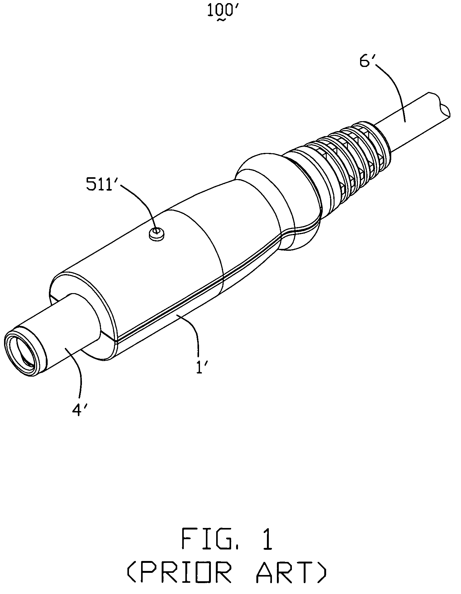
a plug connector and right angle technology, applied in the direction of three-pole connection, coupling device connection, coupling protective earth/shielding arrangement, etc., can solve the problem that the conventional dc power plug connector is not adapted to mate with some electrical devices

Inactive Publication Date: 2010-07-13
HON HAI PRECISION IND CO LTD
View PDF7 Cites 32 Cited by
  • Summary
  • Abstract
  • Description
  • Claims
  • Application Information

AI Technical Summary

Problems solved by technology

However, the conventional DC power plug connector is not adapted to mate with some electrical devices which need right-angle typed connector.

Method used


Image

  • Plug connector with right angle cover
  • Plug connector with right angle cover
  • Plug connector with right angle cover

Examples


Embodiment Construction

[0016]Reference will now be made in detail to a preferred embodiment of the present invention.

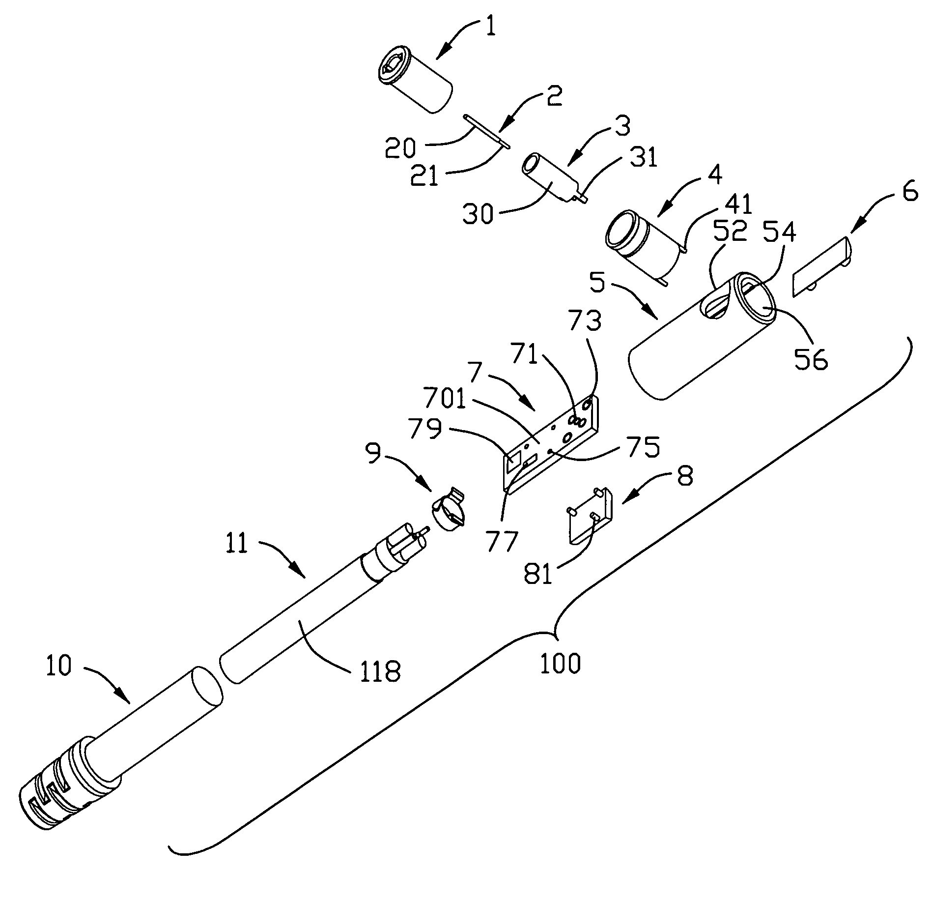
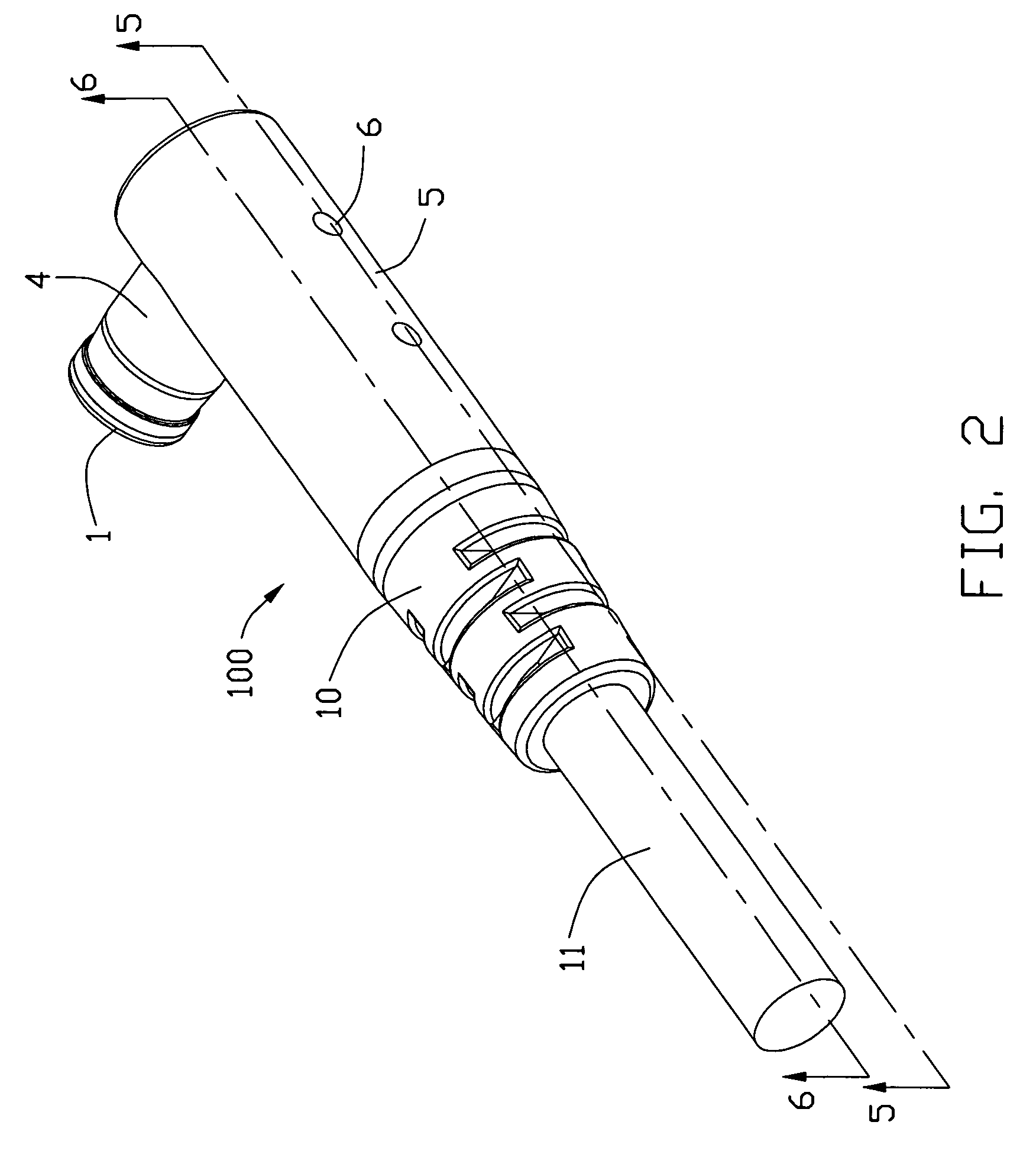
[0017]Referring to FIGS. 1 to 2, a power cord cable assembly 100 made in accordance with the present invention is used to exchange electrical signals when connected to the complementary connector (not shown). The cable assembly 100 comprises a housing 1, a first contact 2 received in center of the housing 1 for transmitting signals, a second contact 3 received in the housing and around the first contact 2 for transmitting power, a grounding shield 4 arranged around the housing 1, a metal cover 5 electrically connected to the grounding shield 4, a light pipe 6 received in the metal cover 5, a printed circuit board (PCB) 7 received in the metal cover 4, a Light-Emitting Diode (LED) mold 8 received in the metal cover 5, a cable 11, a crimp portion 9 increasing strain relief (SR) retention force and a dielectric mold 10 filled in the grounding shield 5.

[0018]Referring to FIGS. 2 to 6, the housi...


PUM


Abstract

A plug connector for mating with a complementary connector includes a mating plug connector and an electrical connector. The mating plug connector includes a housing, a plurality of contacts received in the housing and spaced apart from each other, and a grounding shield surrounding the housing. The electrical connector is perpendicular to the mating plug connector and includes a metal cover, and an electric substrate received in the metal cover and electrical connected to the contacts of the mating plug connector.

Description

BACKGROUND OF THE INVENTION[0001]1. Field of the Invention[0002]The present invention relates generally to a plug connector, and more particularly to a plug connector assembled with right angle cover.[0003]2. Description of the Prior Art[0004]Electrical interconnection is generally made by two connectors, i.e. a plug connector and a mating female connector. In general, the female connector sits on the electronic device, while the plug connector is terminated at an end of a cable.[0005]Direct current (DC) power plug connector is one type of electrical plug connections used to provide DC power for electrical apparatus. Reference to FIG. 1, a prior art DC power cord cable assembly 100′ with a LED is shown. The DC power cord assembly 100′ comprises a mating plug connector 4′ and an insulative housing 1′ received one end of a cable 6′, some electrical components (not shown) are disposed in the housing 1′ for connection of the cable 6′ and the mating plug connector 4′, and a LED pilot lam...

Claims


Application Information

Patent Timeline
Patent Type & Authority Patents(United States)
IPC IPC(8): H01R12/00
CPCH01R13/648H01R13/6658H01R13/7175H01R24/38H01R2105/00
Inventor WU, JERRY
Owner HON HAI PRECISION IND CO LTD
Why Eureka
Try Eureka