Resistive current limiter

a resistive current limiter and resistive technology, applied in the direction of superconducting superconducting switchable devices, emergency protective arrangements for limiting excess voltage/current, non-adjustable resistors, etc., can solve the problem of very thin insulating buffer layer dielectric breakdown, low resistance, etc., to reduce the danger of micro crack formation, increase the radius of curvature, and stabilize against vibration

Inactive Publication Date: 2010-07-20
THEVA DUENNSCHICHTTECHN
View PDF13 Cites 5 Cited by
  • Summary
  • Abstract
  • Description
  • Claims
  • Application Information

AI Technical Summary

Benefits of technology

[0033]Preferably only short hollow forms are used between which the tape is self-supporting. Particularly preferred short hollow forms are thin plates or foils standing across the tape and having cut-outs or apertures of hollow cross section with at least one section of the tape extending inside. Then the tape can evade the forces of bubble formation, thermal expansion and magnetic fields without buckling or cracking which would destroy it.
[0056]Finally, it is preferable if the tape conductor in its current limiting state can develop and sustain an areal power density of at least 50 kW / m2 for a time span of 100 ms and it is particularly preferable if it can develop and sustain without damage at least 250 kW / m2 for a time span of 100 ms. This way it is assured that the voltage drop along the tape conductor in the limiting state is sufficiently large.

Problems solved by technology

In both cases, material problems and cost reasons have prevented commercial use.
Both the flexibility and the long length are resulting in technical problems which are specific for CC-SFCL.
During the limiting state large voltage drops can occur locally resulting in substantial potential differences between the superconductor and the substrate which lead to dielectric breakdown of the very thin insulating buffer layer.
Because these weak spots are of limited size, their resistance is too low, however, to limit the current efficiently.
Therefore they heat up by Joule heating and destroy themselves before the rest of the conductor has become normal.
Still unsolved according to the state of art are problems which are connected with the arrangement and mounting of the tapes.
Due to the bubble formation there are substantial forces acting on the tape which can bend the tape and crack the superconducting layer, or they can lead to contact between different tape sections and to short circuits.
In addition, temperature differences between the front and back side of the tape lead to bending similar to a bimetal (thermal deformation).
This can result in large forces if the tape is not mounted properly.
Because current is alternating the tape can vibrate if it is improperly mounted.
The forces can become excessive when overcurrent arises.
The resulting problems are the same as with gas development and thermal expansion.Overheating due to hindered coolant access:The access of the coolant to the tape will be hindered when even small spots of the tape are touched by mounting elements or other parts.
As a consequence, such areas are heating up faster than the rest.
This is detrimental for the long term behaviour on a scale of some tens of milliseconds, because these areas will burn out before the mechanical switch in series with the SFCL can take over.
Also in this configuration the access of coolant is hindered.
Although liquid nitrogen, for example, has a very high dielectric strength, it will be considerably degraded in the presence of gas bubbles.
Hence, just during the limiting state, when the coolant is boiling, there is a danger of electric breakdown between parts at different potential level.Reduction of critical current in self field:The critical current of superconductors decreases in magnetic fields.
With an improper setup of the SFCL the current to be limited can by itself build up a field sufficiently high to lower the switching level of the SFCL substantially and hence to reduce the switching power of the device.
However, due to the required spacing between windings the situation is different for CC and other measures of compensation have to be taken.Lacking mechanical stabilityThe tape is flexible and has therefore no mechanical stability.

Method used


Image

  • Resistive current limiter
  • Resistive current limiter
  • Resistive current limiter

Examples


Embodiment Construction

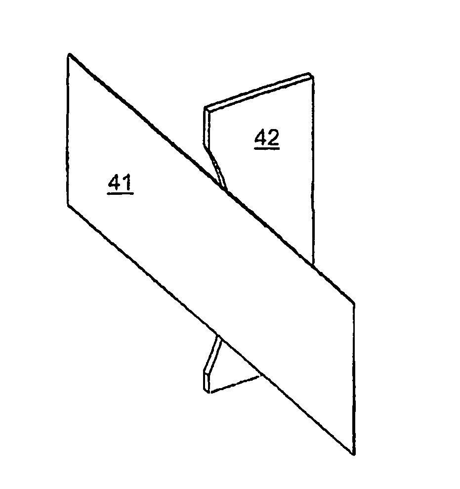
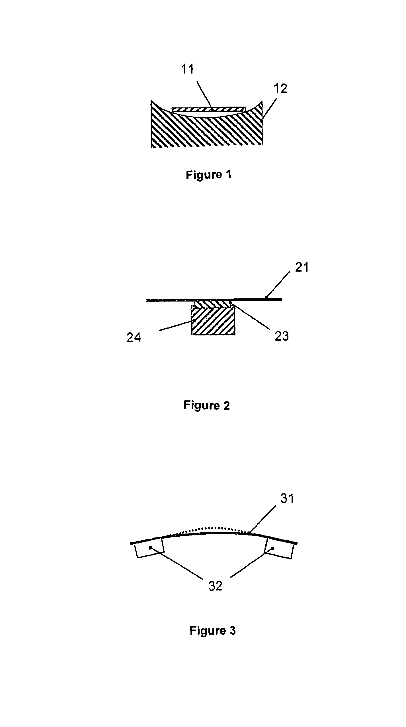
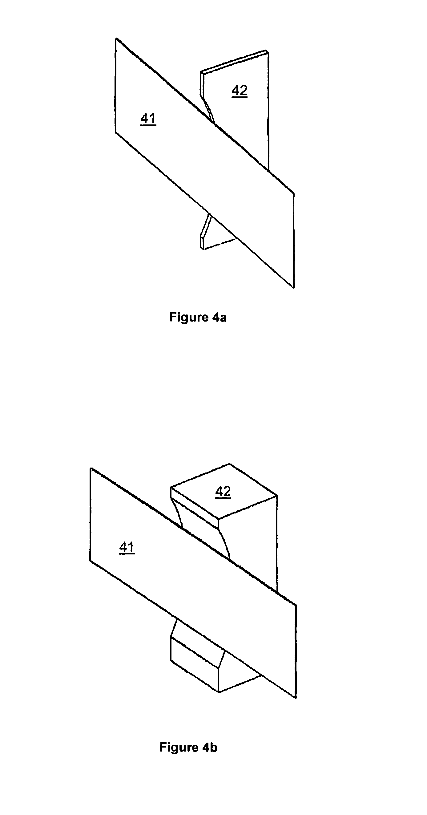
[0071]This section describes presently preferred embodiments of the invention in detail. Thereby the following definitions will be used:[0072]HTS: high temperature superconductor, here in the form of thin films[0073]CC: coated conductor, HTS-coated metal tape[0074]SFCL: superconducting fault current limiter[0075]tape conductor: here synonymous to conductor tape, the tape, and CC[0076]principal surfaces: major or main surfaces; the surface of the CC coated with the superconductor or the opposite surface[0077]edge regions: lateral surfaces of the tape including the edges and including possible margins without HTS coating;[0078]front surface: principal surface with HTS coating (in case of one-sided HTS coating)[0079]rear surface: principal surface without HTS coating (in case of one-sided HTS coating)[0080]tape sections: different sections of the tape which can touch each other or interfere with one another[0081]thermal deformation: elastic or plastic bending caused by differential the...


PUM


Abstract

According to a first aspect the present invention relates to a fault current limiter formed by a conductor tape (11, 41, 51, 61, 71) coated with a high temperature superconductor and having at least one mounting element (12, 42, 52, 62, 72) which is essentially holding the conductor tape solely on one or more edge regions in such a way that the principal surfaces of the tape cannot get in touch with the mounting element.According to a second aspect the present invention relates to a fault current limiter formed by a conductor tape coated with a high temperature superconductor and comprising at least one mounting element (23, 24) which is contacting the conductor tape on one or on both major surfaces in an electrically conducting manner such that the conductor tape (21) in its normal conducting state is electrically shunted by the mounting element (23) in the contact region.

Description

[0001]This application is a U.S. patent application claiming priority on EP 06 004 214.0 filed Mar. 2, 2006, the entire contents of which are hereby incorporated herein by reference.TECHNICAL FIELD[0002]The invention is related to a superconducting resistive fault current limiter.DESCRIPTION OF THE PRIOR ART[0003]Superconducting fault current limiters (SFCL) can be used to protect electrical installations and power grids from overload. The action of a SFCL is quite simple. During normal operation the conductor is in the superconducting state and hence nearly lossless. When overcurrent arises, the superconductor is switching very quickly into the normal conducting state where it is highly resistive and hence limits the current to an acceptable level.[0004]The advantage of the SFCL in comparison with conventional mechanical switches are their very much shorter switching times. On the other hand they develop substantial amounts of heat in the normal state, so that they can sustain thei...

Claims


Application Information

Patent Timeline
Patent Type & Authority Patents(United States)
IPC IPC(8): H01C7/00
CPCH01L39/16H10N60/30H01H36/00
Inventor PRUSSEIT, WERNERKINDER, HELMUT
Owner THEVA DUENNSCHICHTTECHN
Why Eureka
Try Eureka