
Method and apparatus for time-divisional display panel drive

a display panel and drive technology, applied in the direction of static indicating devices, picture reproducers using solid-state color displays, instruments, etc., can solve the problems of reducing reduce the influence of vertical segments of uneven brightness, and reduce the influence of image quality

Inactive Publication Date: 2010-07-20
RENESAS ELECTRONICS CORP
View PDF35 Cites 3 Cited by
  • Summary
  • Abstract
  • Description
  • Claims
  • Application Information

AI Technical Summary

Benefits of technology

[0026]This method effectively reduces vertical segments of uneven brightness, because the firstly-driven pixel, which experiences considerable variation in the drive voltage thereacross, exhibits a reduced influence on the image quality due to the low spectral luminous efficacy.
[0027]In a preferred embodiment, the first to p-th pixels are driven during a horizontal scanning period in the order from low to high spectral luminous efficacies. This achieves further improvement of the image quality.

Problems solved by technology

This method effectively reduces vertical segments of uneven brightness, because the firstly-driven pixel, which experiences considerable variation in the drive voltage thereacross, exhibits a reduced influence on the image quality due to the low spectral luminous efficacy.

Method used


Image

  • Method and apparatus for time-divisional display panel drive
  • Method and apparatus for time-divisional display panel drive
  • Method and apparatus for time-divisional display panel drive

Examples


Embodiment Construction

[0057]Referring now to drawings, various preferred embodiments of the present invention will be described in detail. It should be noted that same reference numerals denoted same or similar components in the drawings.

Display Device Structure

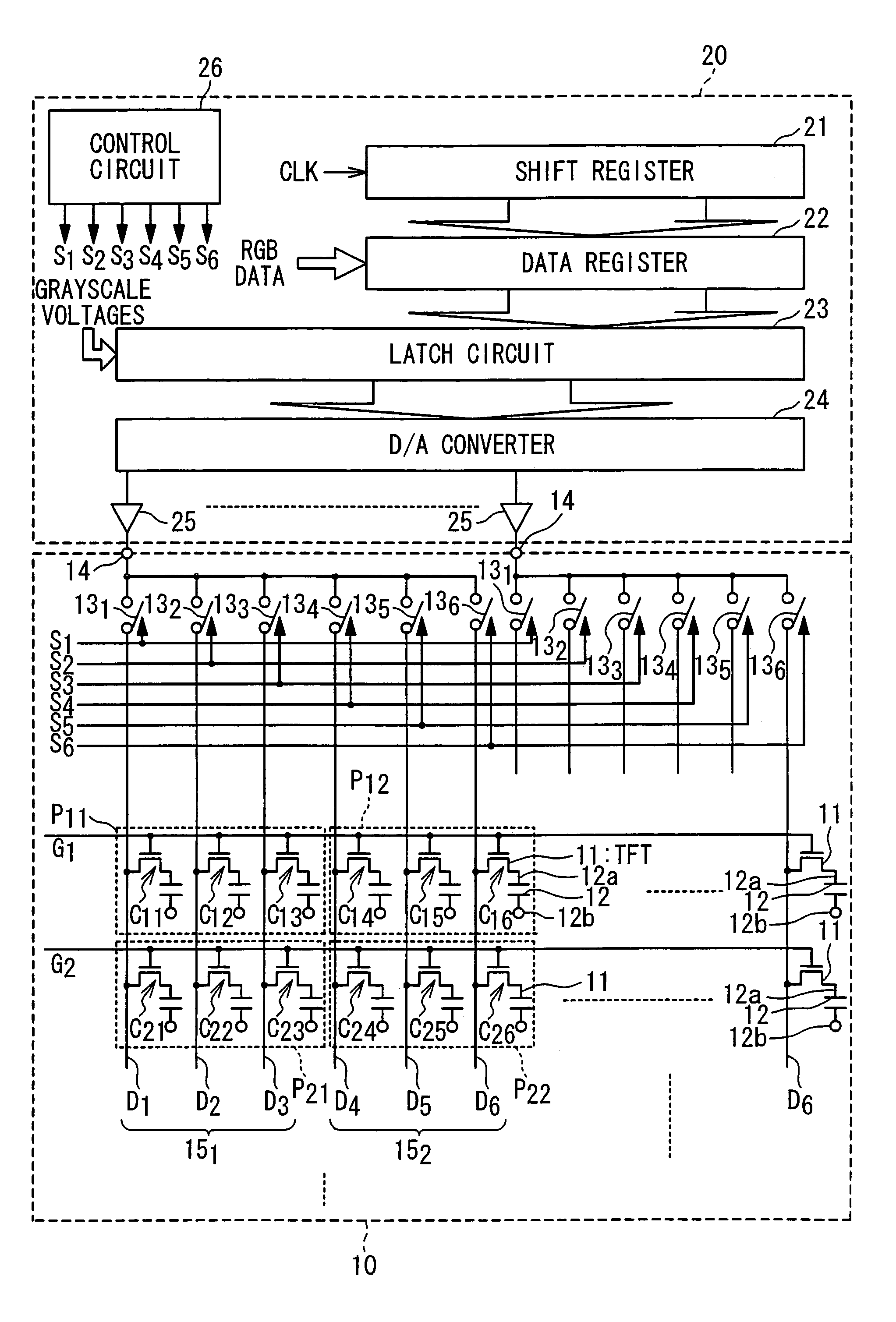
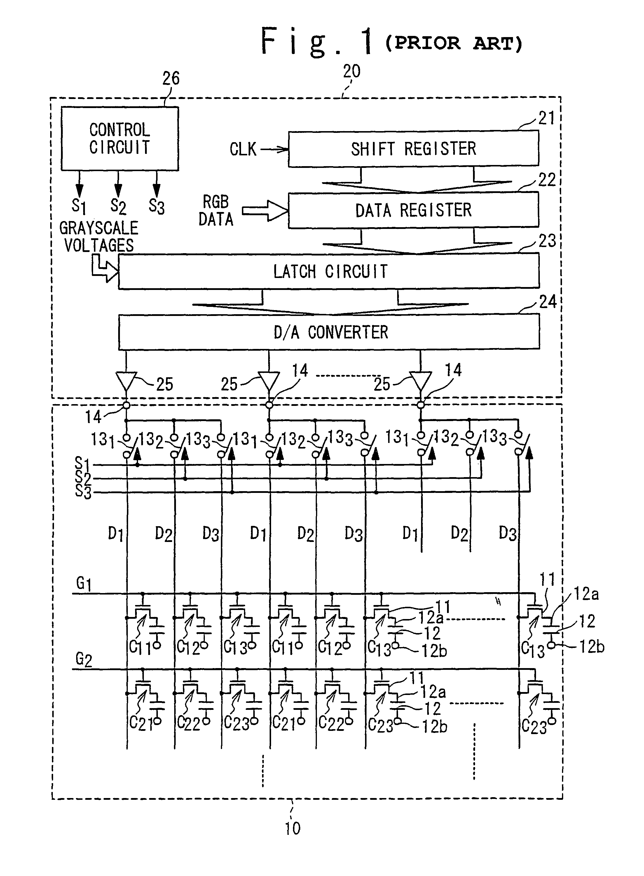
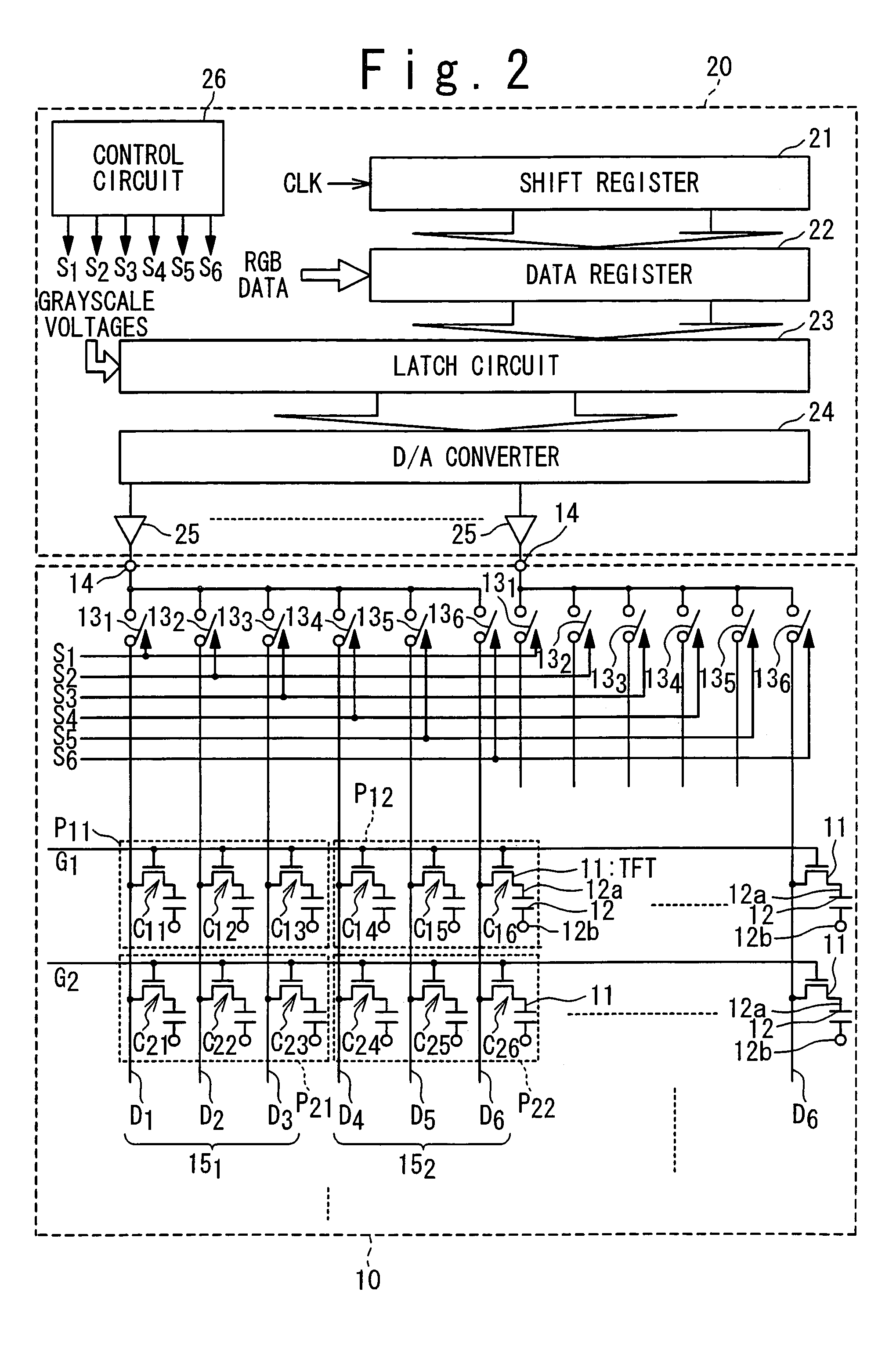
[0058]In one embodiment, as shown in FIG. 2, a display panel driving method according to the present invention is applied to a display device adapted to time-divisional driving of six signal lines with a single amplifier. It should be noted that the structure of the display device shown in FIG. 2 is substantially identical to that of the display device shown in FIG. 1 except for that the number of the signal lines associated with a single amplifier is different from that of the display device shown in FIG. 1. The display device in this embodiment will be briefly described in the following.

[0059]The display device is provided with a liquid crystal display panel 10 and a driver 20. The liquid crystal display panel 10 is equipped with signal lines D1...


PUM

PropertyMeasurementUnit
spectral luminous efficacyaaaaaaaaaa
spectral luminous efficaciesaaaaaaaaaa
colorsaaaaaaaaaa

Abstract

A method is provided for driving a display device including first to p-th pixels associated with different colors with p being integers equal to or more than three. The method is composed of a step of time-divisionally driving the first to p-th pixels. In the time-divisionally driving, the pixel associated with the color exhibiting the lowest spectral luminous efficacy among the colors is firstly driven.

Description

BACKGROUND OF THE INVENTION[0001]1. Field of the Invention[0002]The present invention generally relates to methods and apparatuses for driving display panels. More specifically, the present invention relates to methods and apparatuses adapted to drive signal lines within display panels in a time divisional manner.[0003]2. Description of the Related Art[0004]Recent display panels are composed of an increased number of signal lines (or data lines) with reduced intervals therebetween; this is a basic requirement for high-resolution display panels. The increase in the number of signal lines and / or the reduction in the intervals thereof, however, undesirably cause a problem in providing electrical connection between the display panel and the display panel driver with external wiring lines. The reduction in the intervals of the signal lines undesirably reduce pitches allowed to the external connecting wiring lines, so that the display panel experiences a difficulty in achieving electrical...

Claims


Application Information

Patent Timeline
Patent Type & Authority Patents(United States)
IPC IPC(8): G09G3/36G02F1/133G09G3/20G09G5/00H04N9/12H04N9/30
CPCG09G3/3688G09G3/2003G09G3/3607G09G2310/027G09G2310/0297
Inventor TOEDA, MASAHIRONOSE, TAKASHI
Owner RENESAS ELECTRONICS CORP
Learn More