
Radiation imaging apparatus, control method for radiation imaging apparatus, and non-transitory computer-readable storage medium

a control method and radiation imaging technology, applied in the direction of color television details, television system details, television systems, etc., can solve the problems of requiring a longer time to perform image capture to obtain dark current images, vertical line and block artifacts in radiation images, etc., to achieve accurate acquisition of noise components, longer time to perform image capture, and more influence on image quality

Active Publication Date: 2020-08-11
CANON KK
View PDF8 Cites 1 Cited by
  • Summary
  • Abstract
  • Description
  • Claims
  • Application Information

AI Technical Summary

Benefits of technology

[0003]Low-frequency noise (1 / f noise) as a type of FPN caused by semiconductor elements constituting signal paths to which signals are output from pixels sometimes exerts more influence on image quality than random noise, causing vertical line and block artifacts in radiation images. To obtain correction image data, in order to more accurately obtain a noise component originating from semiconductor elements arranged on a signal path, it is necessary to obtain a plurality of dark current images. However, in the correction image data generation method disclosed in Japanese Patent Laid-Open No. 2014-30151, with an increase in the number of dark current images used for the generation of correction image data, it requires a longer time to perform image capturing to obtain dark current images. No radiation image can be captured while correction image data is generated. It is therefore required to shorten the time taken to generate correction image data.
[0004]Some embodiments of the present invention provide techniques advantageous in shortening the time to generate correction image data.
[0006]According to some other embodiment, a control method for a radiation imaging apparatus including an image capturing unit configured to capture a radiation image and a signal processing unit, wherein the image capturing unit includes a plurality of pixels each including a conversion unit configured to convert radiation into electric charge and a holding unit configured to hold a signal corresponding to electric charge of the conversion unit, wherein the method comprises: causing the holding unit to hold a first signal corresponding to electric charge generated by the conversion unit by one image capturing operation without irradiation with radiation, and causing the signal processing unit to generate correction image data based on the plurality of first signals nondestructively read out from the holding unit over a plurality of times while the holding unit holds the first signals, and causing the signal processing unit to correct radiation image data captured by the image capturing unit during irradiation with radiation by using the correction image data, is provided.

Problems solved by technology

Low-frequency noise (1 / f noise) as a type of FPN caused by semiconductor elements constituting signal paths to which signals are output from pixels sometimes exerts more influence on image quality than random noise, causing vertical line and block artifacts in radiation images.
However, in the correction image data generation method disclosed in Japanese Patent Laid-Open No. 2014-30151, with an increase in the number of dark current images used for the generation of correction image data, it requires a longer time to perform image capturing to obtain dark current images.

Method used


Image

  • Radiation imaging apparatus, control method for radiation imaging apparatus, and non-transitory computer-readable storage medium
  • Radiation imaging apparatus, control method for radiation imaging apparatus, and non-transitory computer-readable storage medium
  • Radiation imaging apparatus, control method for radiation imaging apparatus, and non-transitory computer-readable storage medium

Examples


first embodiment

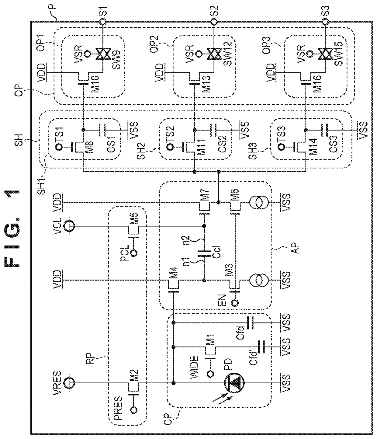
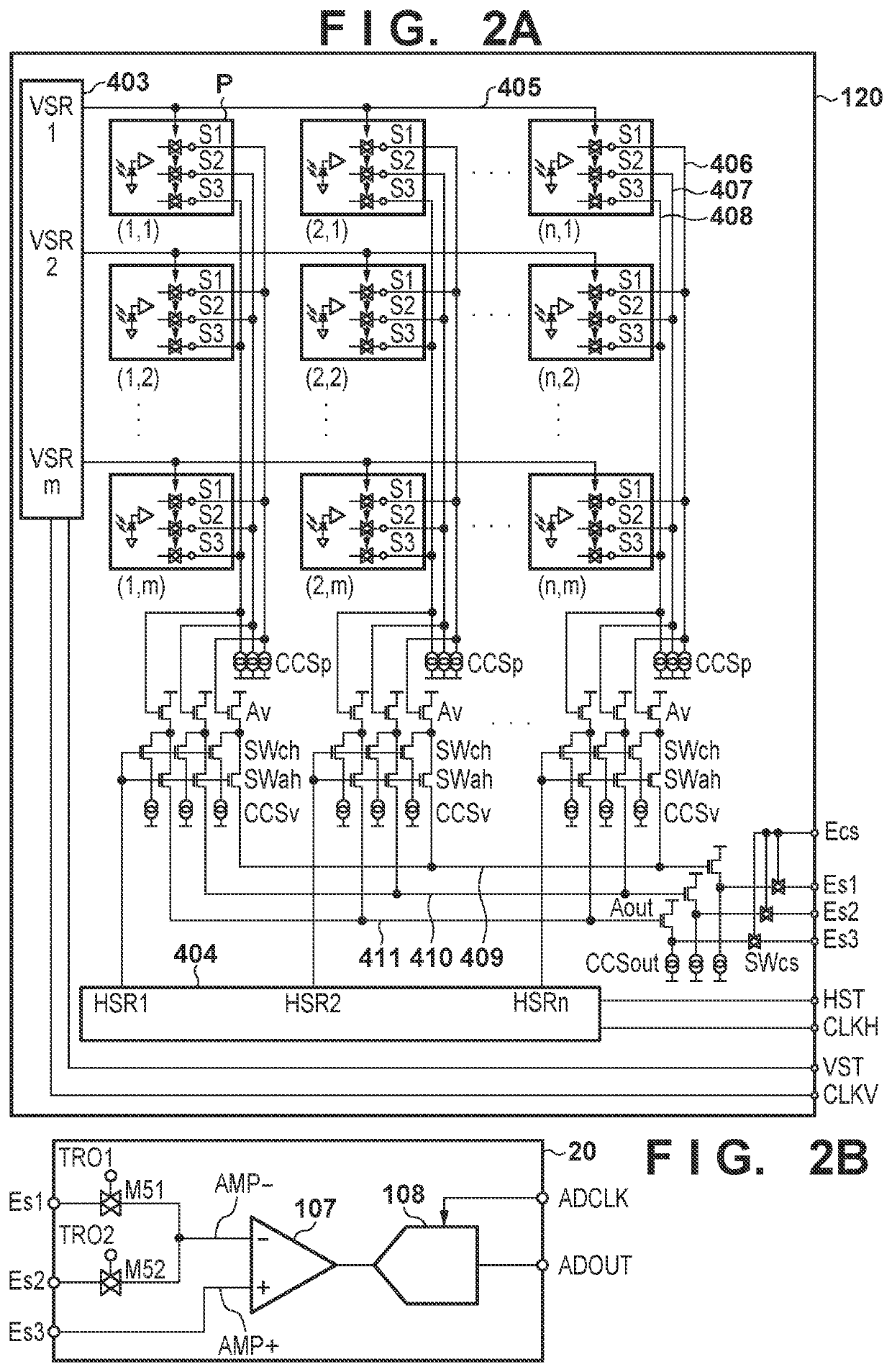
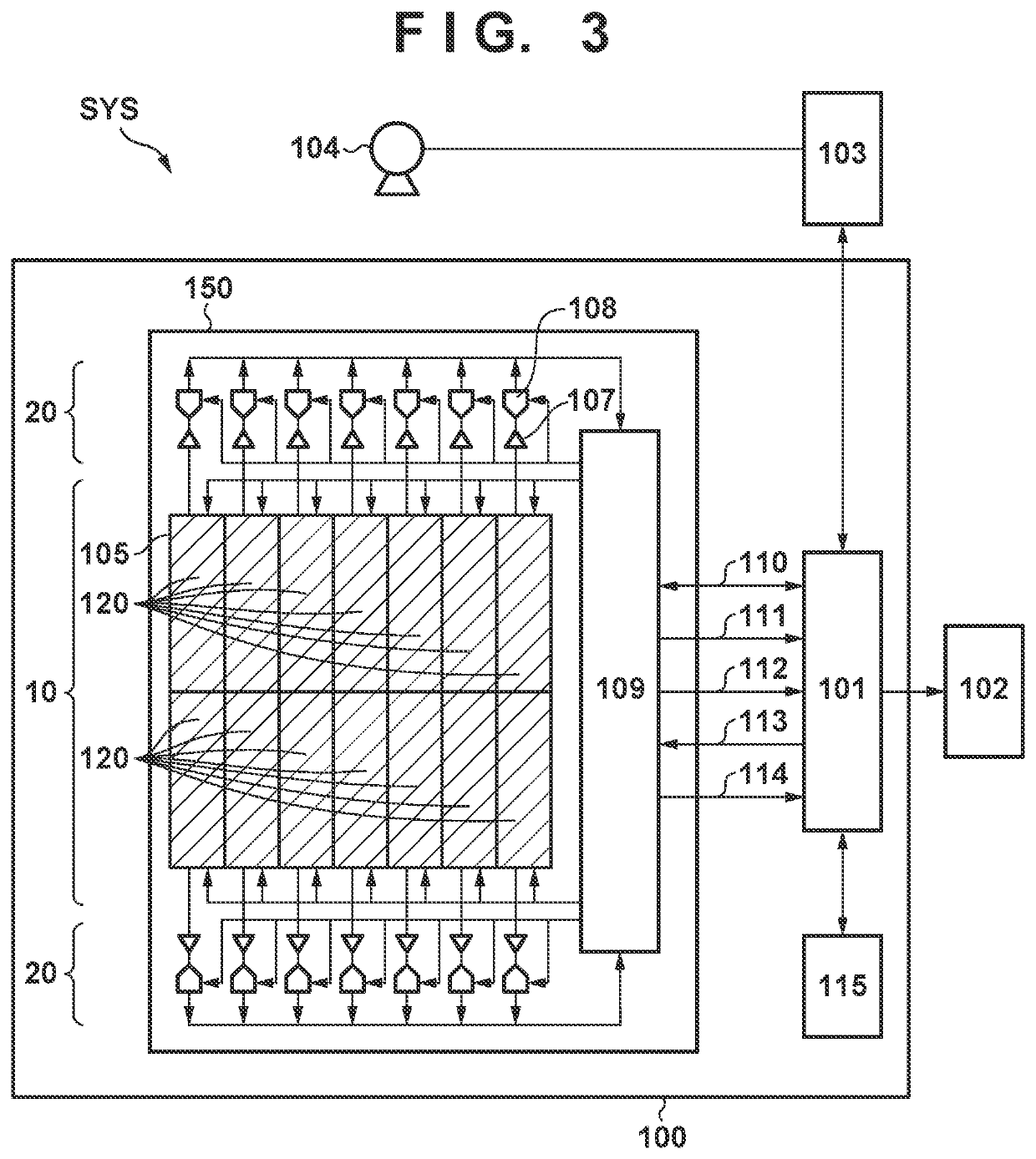
[0025]The configuration of a radiation imaging apparatus and a control method (driving method) according to the present invention will be described with reference to FIGS. 1 to 7. FIG. 1 is an equivalent circuit diagram showing an example of the configuration of each pixel P arrayed in a pixel array of an image capturing unit 150 for detecting and capturing an image of radiation in a radiation imaging apparatus 100 according to the present invention. The pixel P includes a conversion unit CP, an amplification unit AP, a reset unit RP, holding units SH, that is, SH1 to SH3, and output units OP, that is, OP1 to OP3. In this embodiment, the configuration of each of these components of the pixel P is implemented by an electronic circuit. For example, the conversion unit CP is implemented by a conversion circuit.

[0026]The conversion unit CP for converting radiation into electric charge includes a photodiode PD, a transistor M1, an FD (Floating Diffusion) capacitor Cfd, and an additional ...

second embodiment

[0136]FIG. 12 is a timing chart showing an example of a driving method of generating two types of dark images with different accumulation periods by one image capturing operation. For the sake of simplicity, FIG. 12 explains a case in which an image capturing mode without an additional capacitor Cfd′ is set. However, the embodiment may be configured to generate dark images with different sensitivities by connecting the additional capacitor Cfd′ as in the second embodiment described above.

[0137]First of all, an image capturing mode is set before image capturing. In this image capturing mode, the sensitivity of a pixel P corresponds to a sensitivity set with only an FD capacitor Cfd without an additional capacitor Cfd′. As in the timing chart in the first embodiment shown in FIGS. 4 and 5, therefore, a panel control unit 109 inactivates a control signal WIDE. In addition, the panel control unit 109 makes settings for driving to generate two types of dark images with different accumula...

third embodiment

[0168]An operation for generating correction image data will be described next with reference to FIG. 15. Differences from the third embodiment will be mainly described below.

[0169]The processing in steps S301 to S308 in FIG. 15 is the same as that in the third embodiment described above. The panel control unit 109 drives the image capturing panel 105 and a signal readout unit 20 in accordance with the timing chart shown in FIG. 14 instead of the timing chart of FIG. 12 according to the third embodiment.

[0170]In step S309′, upon completion of a preset number of periods R1 to read out the accumulation signals S1 in the accumulation period T1, the panel control unit 109 drives the image capturing panel 105 and the signal readout unit 20 in accordance with the timing chart shown in FIG. 14. The panel control unit 109 A / D-converts the accumulation signal S2 and the reset signal S3 in the accumulation period T2, which are held in each pixel P, and transfers the resultant data as pixel da...


PUM


Abstract

A radiation imaging apparatus is provided. The apparatus comprises an image capturing unit and a signal processing unit. The image capturing unit includes a plurality of pixels each including a conversion unit configured to convert radiation into electric charge and a holding unit configured to hold a signal corresponding to electric charge of the conversion unit. The holding unit holds a first signal corresponding to electric charge generated by the conversion unit by one image capturing operation without irradiation with radiation. The signal processing unit generates correction image data based on the plurality of first signals nondestructively read out from the holding unit over a plurality of times while the holding unit holds the first signals, and corrects radiation image data captured by the image capturing unit during irradiation with radiation by using the correction image data.

Description

BACKGROUND OF THE INVENTIONField of the Invention[0001]The present invention relates to a radiation imaging apparatus, a control method for the radiation imaging apparatus, and a non-transitory computer-readable storage medium.Description of the Related Art[0002]In medical imaging diagnosis and nondestructive inspection, a radiation imaging apparatus using an FPD (Flat Panel Detector) formed from a semiconductor material is widely used. In the FPD, FPN (Fixed Pattern Noise) is caused by dark currents generated in pixels, and variations of semiconductor elements such as transistors constituting pixels and / or signal paths through which signals output from pixels. Japanese Patent Laid-Open No. 2014-30151 discloses how to obtain a plurality of dark current images by image capturing without irradiation with radiation to suppress the influence of FPN and to correct a radiation image by using correction image data obtained by averaging processing of a plurality of dark current images.SUMMA...

Claims


Application Information

Patent Timeline
Patent Type & Authority Patents(United States)
IPC IPC(8): H04N5/361H04N5/355H04N5/363G01T1/17G01T1/24H04N5/32H04N5/3745H04N5/341
CPCH04N5/341H04N5/3559H04N5/32G01T1/17H04N5/361H04N5/37452H04N5/363G01T1/24H04N25/40H04N25/63H04N25/771H04N25/59H04N25/65
Inventor KOBAYASHI, SHIGEO
Owner CANON KK
Learn More