Electronic watermark embedding apparatus for selectively embedding electronic watermark information in different frequency components of image data and electronic watermark embedding method
a technology embedding apparatus, which is applied in the direction of electrical apparatus, instruments, computing, etc., can solve the problems that the resistance property of electronic watermark information to be embedded in the component having the strong resistance property is limited to the important information, so as to prevent the deterioration of image quality and improve the resistance property of electronic watermark
- Summary
- Abstract
- Description
- Claims
- Application Information
AI Technical Summary
Benefits of technology
Problems solved by technology
Method used
Image
Examples
first exemplary embodiment
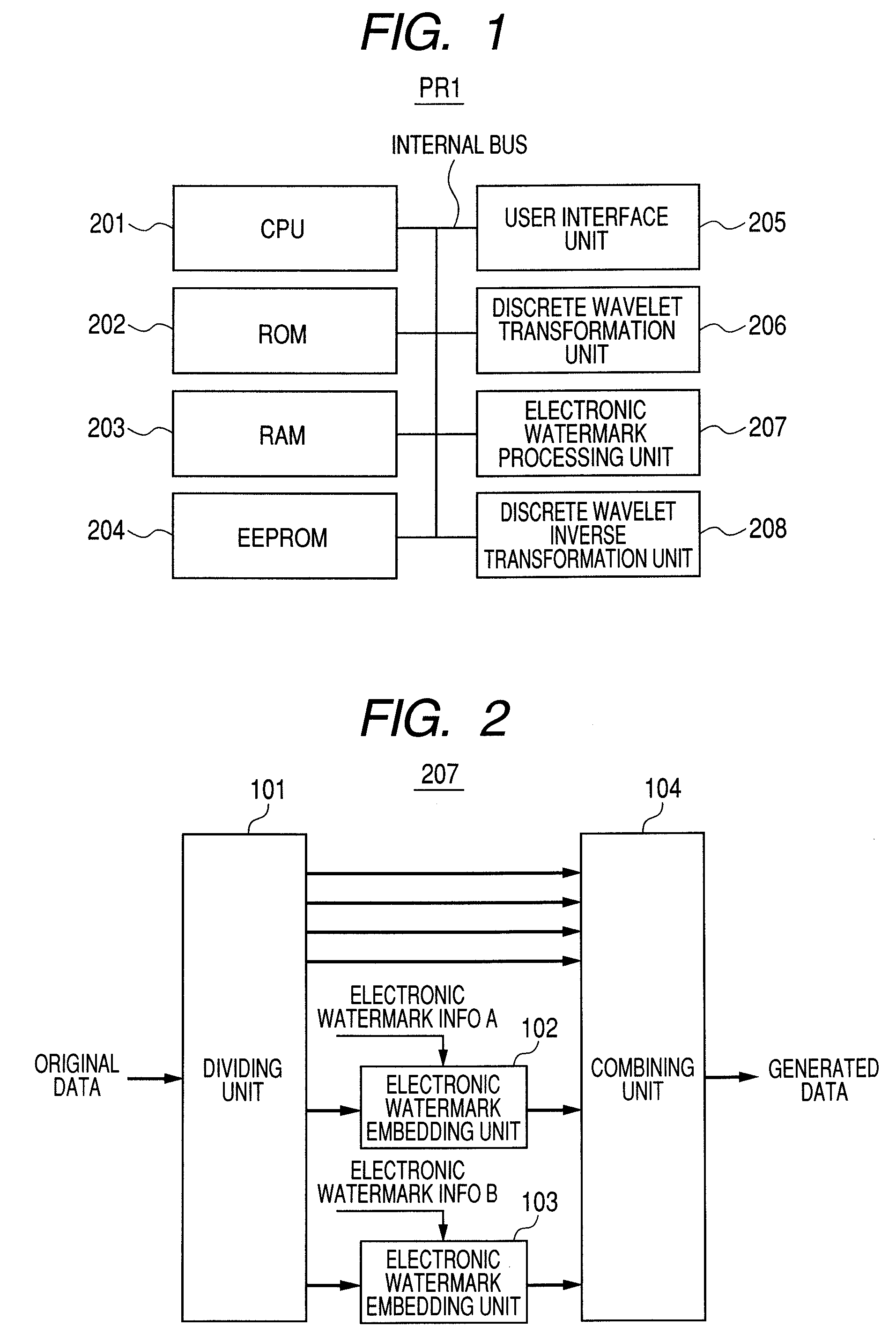
[0048]FIG. 1 is a block diagram illustrating an image processing apparatus PR1 of a first exemplary embodiment of the present invention.
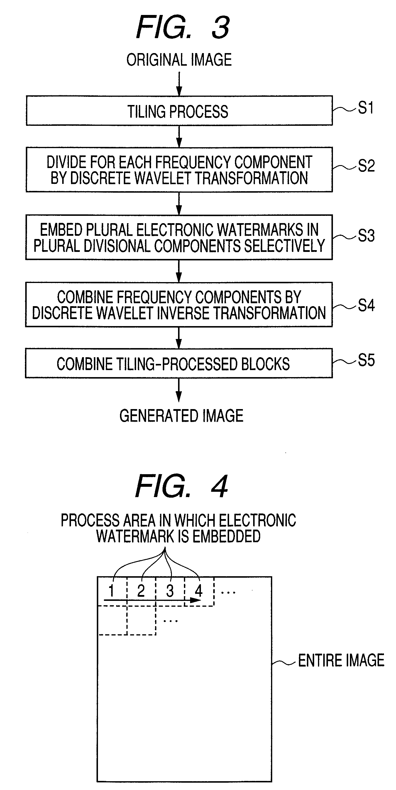
[0049]The image processing apparatus PR1 of the first exemplary embodiment is an apparatus for dividing image data into frequency components by the use of a discrete wavelet transformation to embed an electronic watermark in the image data.
[0050]The image processing apparatus PR1 includes a central processing unit (CPU) 201, a read only memory (ROM) 202, a random access memory (RAM) 203, an electrically erasable, programmable read-only memory (EEPROM) 204, a user interface unit 205, a discrete wavelet transformation unit 206, the electronic watermark processing unit 207, and a discrete wavelet inverse transformation unit 208.
[0051]The CPU 201 controls the image processing apparatus PR1. The ROM 202 stores programs for controlling the image processing apparatus PR1. The RAM 203 is a data readable and writable memory. The EEPROM 204 is a memory capabl...
application example of first exemplary embodiment
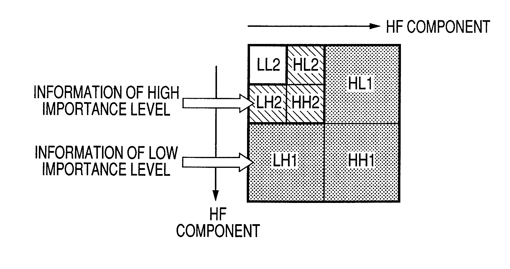
[0078]The first exemplary embodiment embeds an electronic watermark in the highest frequency components and the next highest frequency components. As an application example of the first exemplary embodiment, flexible electronic watermark embedding capable of coping with both of the resistance property and the image quality is conceivable.
[0079]FIG. 10 is a diagram for describing a method of embedding a plurality of pieces of electronic watermark information, which method is the application example of the first exemplary embodiment.
[0080]Three-stage division of a tile image is performed, and four stages of frequency division are performed. The high frequency components HH1, HL1, and LH1 are components having the highest frequencies. The second high frequency components HH2, HL2, and LH2 are the frequency components having the highest frequencies next to those of the high frequency components HH1, HL1, and LH1. Third high frequency components HH3, HL3, and LH3 are the frequency compon...
second exemplary embodiment
[0082]FIG. 11 is a block diagram illustrating an image processing apparatus PR2 of a second exemplary embodiment of the present invention.
[0083]The first exemplary embodiment is the one executing each unit in a separated block. The second exemplary embodiment is the one executing the whole process thereof in one block.
[0084]The image processing apparatus PR2 includes a CPU 1101, a ROM 1102, a RAM 1103, an EEPROM 1104, a user interface unit 1105, and an electronic watermark processing unit 1106.
[0085]The CPU 1101 controls the image processing apparatus PR2. The ROM 1102 stores programs for controlling the image processing apparatus PR2. The RAM 1103 is a data readable and writable memory.
[0086]The EEPROM 1104 can hold data even when the power source thereof is intercepted. The user interface unit 1105 communicates with external equipment of the apparatus PR2. The electronic watermark processing unit 1106 performs the process of embedding an electronic watermark.
[0087]FIG. 12 is a con...
PUM
 Abstract
Description
Claims
Application Information
 - R&D
- Intellectual Property
- Life Sciences
- Materials
- Tech Scout
- Unparalleled Data Quality
- Higher Quality Content
- 60% Fewer Hallucinations
Browse by: Latest US Patents, China's latest patents, Technical Efficacy Thesaurus, Application Domain, Technology Topic, Popular Technical Reports.
© 2025 PatSnap. All rights reserved.Legal|Privacy policy|Modern Slavery Act Transparency Statement|Sitemap|About US| Contact US: help@patsnap.com


