
Installation for assembling fuel cell membranes

a technology of fuel cell membranes and assembly devices, which is applied in the direction of fuel cells, solid electrolyte fuel cells, electrochemical generators, etc., can solve problems such as difficulty in achieving, and achieve the effect of facilitating the gripping of each membrane by a manipulator

Active Publication Date: 2022-05-10
COMMISSARIAT A LENERGIE ATOMIQUE ET AUX ENERGIES ALTERNATIVES +1
View PDF10 Cites 0 Cited by
  • Summary
  • Abstract
  • Description
  • Claims
  • Application Information

AI Technical Summary

Benefits of technology

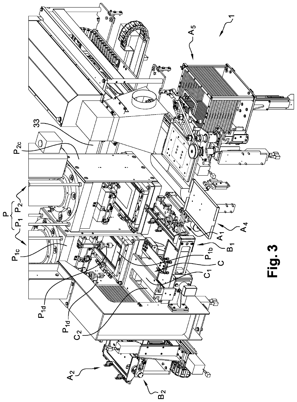
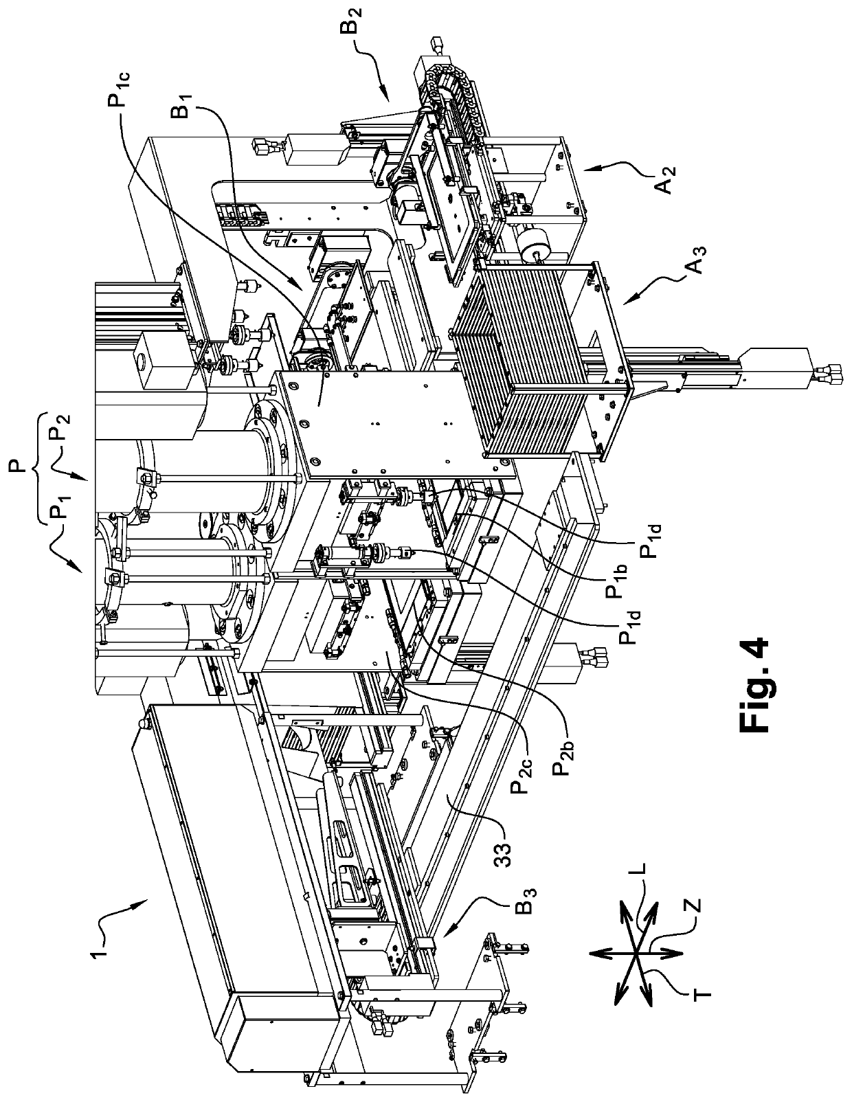
This patent describes a method for making membrane / electrode assemblies for batteries. The method involves arranging the membranes and reinforcing membranes in separate storage stations, and then stacking them on a separate stacking station. A press is used to adapt the heating and cooling zone to the dimensions of the membrane / electrode assembly by changing the compression plate. The resulting assembly is then moved to a pressing and heating station for further processing. The technical effects of this method include improved safety and flexibility in making batteries with customized dimensions.

Problems solved by technology

It is thus possible to accurately stack the electrode and reinforcing membranes on the stacking station, which would be difficult to achieve with a single station comprising the different membranes because of their different respective dimensions (different bulks).

Method used


Image

  • Installation for assembling fuel cell membranes
  • Installation for assembling fuel cell membranes
  • Installation for assembling fuel cell membranes

Examples


first embodiment

[0149]As shown in FIG. 29, in a tray 47′, the first plate 32′ may comprise a first groove 48′ and a second groove 50′ formed on the second face 44′ of the first plate 32′ and forming independent cooling liquid circulation channels, each channel 48′, 50′ including a liquid inlet 48a′, 50a′ and an outlet 48b′, 50b′ in the tray. The first plate 32′ could still include four fluidly independent channels. In order to allow a good distribution of cold and heat, each of the cooling channel(s) and groove(s) is of the coil type. To obtain a good transfer of frigories in the first plate 32′, it is desirable that the distance along a channel 48′, 50′ from input 48a′, 50a′ of each of the channels 48′, 50a′ to the center of the first plate 32′ is less than the distance along the channel from output 48b′, 50b′ of each of the channels 48′, 50′ to the center of the tray 26′. This promotes a circulation of the liquid to the center and then to the rest of the first plate 32′, which allows a better smo...

second embodiment

[0152]FIGS. 31 and 32 represent a tray 52′ comprising two L-shaped parts 54′, 56′ defining a distinct central portion 58′ between them. Each of the two L-shaped parts 54′, 56′ includes a cooling channel 59′ as described above, the central portion being devoid of a cooling channel and made of a thermally insulating material. The channels 59′ of the parts 54′, 56′ are configured to allow coolant to flow around the central portion and then outwards.

[0153]In this embodiment, only one heating cord could be used (not shown), this one surrounding itself around the central portion 58′ like a spiral. The central portion 58′ is also devoid of any heating means.

[0154]It is easy to understand that the shape of the cooling channels is more critical than that of the heating cords because of the longer time required to reduce the temperature by a given number of degrees using a liquid flow than the time required to increase the temperature by the same number of degrees using a resistive type heati...


PUM

PropertyMeasurementUnit
Young's modulusaaaaaaaaaa
thermal conductivity coefficientaaaaaaaaaa

Abstract

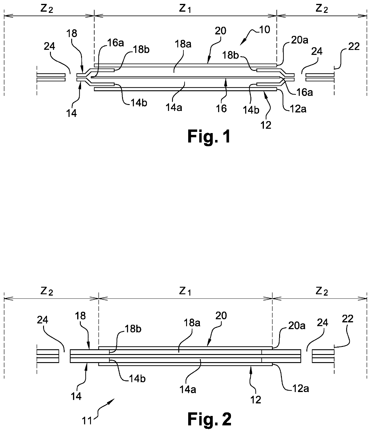
The invention relates to an installation (1) for assembling fuel cell membranes comprising:a first station (A1) for storing electrode membranes, a second station (A2) for storing reinforcing membranes, a station for stacking the membranes of the first (A1) and second (A2) storage stations, and a station (P) for pressing and heating a membrane assembly,means for conveying and handling (B1, B2) the membranes of the first (A1) and second (A2) storage stations, stacking of the stacking station and membrane assembly of the pressing and heating station.

Description

CROSS-REFERENCE TO RELATED APPLICATIONS[0001]This application is a 35 U.S.C. § 371 filing of International Application No. PCT / FR2018 / 051107 filed May 3, 2018, which claims the benefit of priority to French Patent Application No. 1753896 filed May 3, 2017; French Patent Application No. 1753914 filed May 3, 2017; and French Patent Application No. 1753911 filed May 3, 2017, each of which is incorporated herein by reference in its entirety.FIELD OF THE INVENTION[0002]This invention relates to the field of fuel cell membrane / electrode assembling devices.TECHNICAL BACKGROUND[0003]Proton exchange membrane fuel cells, known as PEMFCs, stand for “proton exchange membrane fuel cells” or “polymer electrolyte membrane fuel cells” and have particularly interesting compactness properties. Each cell includes a polymer electrolyte membrane that enables only the passage of protons and not the passage of electrons. The membrane is contacted with an anode on a first side and with a cathode on a secon...

Claims


Application Information

Patent Timeline
Patent Type & Authority Patents(United States)
IPC IPC(8): H01M8/2404H01M8/0267H01M8/0273H01M8/1004H01M8/1086H01M8/10
CPCH01M8/2404H01M8/0267H01M8/0273H01M8/1004H01M8/1093H01M2008/1095Y02E60/50
Inventor BUVAT, PIERRICKCARRIERE, STÉPHANECHAZOT, LAURENTSERRE, JÉRÔMEBOUGY, JEAN-JACQUES
Owner COMMISSARIAT A LENERGIE ATOMIQUE ET AUX ENERGIES ALTERNATIVES
Learn More