
Method and device for the control of a three-phase inverter

a three-phase inverter and control method technology, applied in the direction of electric variable regulation, process and machine control, instruments, etc., can solve the problems of limitations and drawbacks of algorithms

Active Publication Date: 2010-07-20
MARICI HLDG THE NETHERLANDS BV
View PDF9 Cites 7 Cited by
  • Summary
  • Abstract
  • Description
  • Claims
  • Application Information

AI Technical Summary

Benefits of technology

"The present invention provides a method for controlling an inverter to synchronize the output current with the grid voltage in a more efficient manner than conventional methods. The method involves determining the components of a phasor representing the output current from the inverter in a fixed reference system and comparing them with a reference, rotating at the same speed as the phasor representing the grid voltage. An error signal is obtained by comparing the components of the current phasor with the reference, and the inverter is controlled based on this error signal. The invention also includes transforming the three-phase voltages and currents into components in a fixed reference system and using a Clarke transformation or an inverse Clarke transform to obtain the error signal. The control of the maximum output power or current from the inverter is also provided. The invention system includes an electrical power source, a three-phase inverter, and a control to drive the inverter."

Problems solved by technology

Therefore, the problem arises of transferring electrical power in the form of current, with non-constant characteristics, to a grid with an alternating voltage with precise and constant characteristics.
These algorithms have some drawbacks and limits.

Method used


Image

  • Method and device for the control of a three-phase inverter
  • Method and device for the control of a three-phase inverter
  • Method and device for the control of a three-phase inverter

Examples


Embodiment Construction

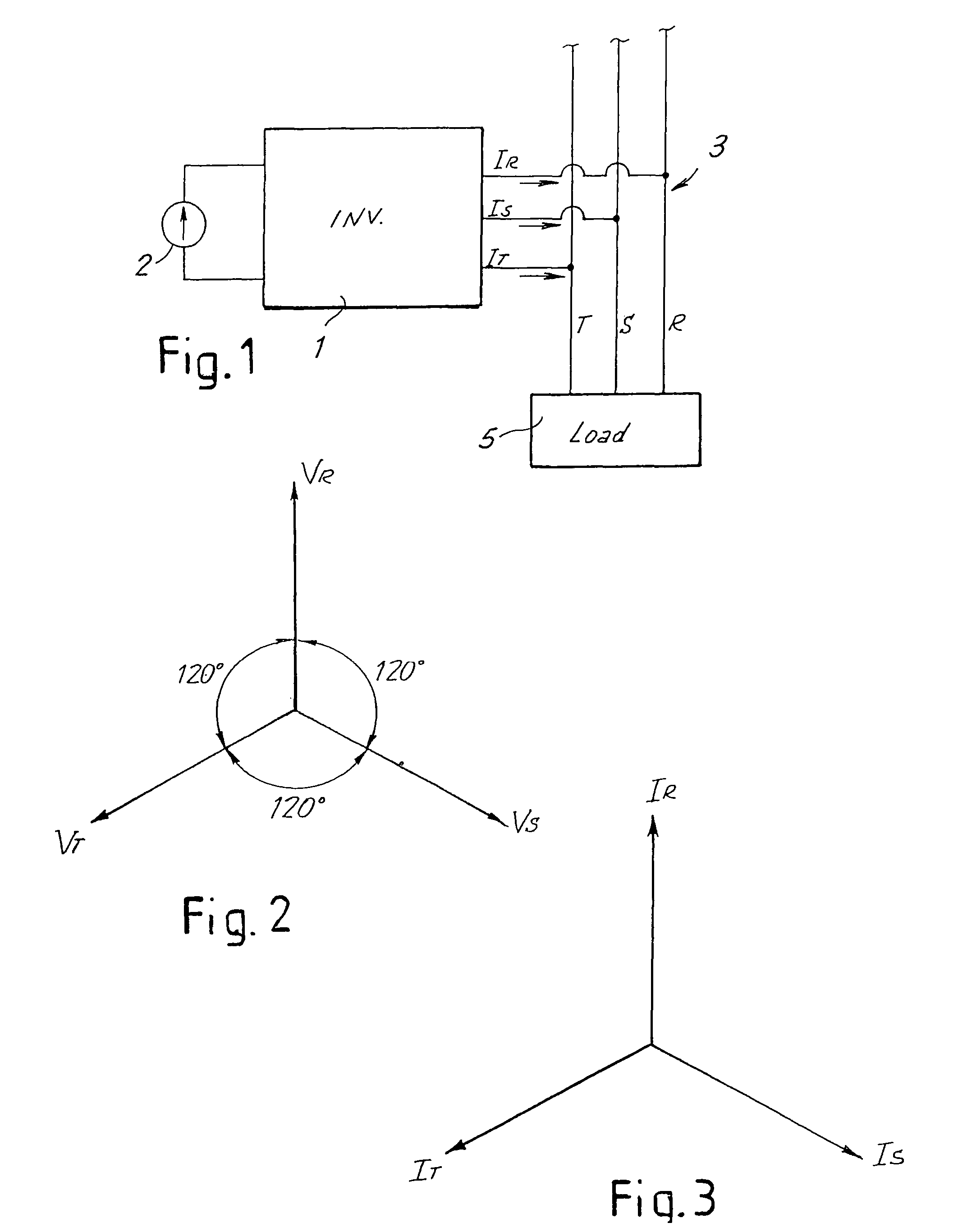
[0039]FIG. 1 schematically shows a three-phase inverter 1, the input of which is connected to a generic electrical power source 2, for example a photovoltaic panel or the like. The output of the three-phase inverter 1 is connected to a three-phase grid 3, the three phases of which are indicated with R, S and T. In the example shown, a generic load 5 is connected to the grid 3. The inverter 1 can be used to at least partly supply electrical power to the load 5 connected to the grid 3. The grid 3 supplies the remaining power required by the load 5 with respect to the power supplied through the inverter 1 from the alternative source 2, or absorbs the excess power supplied by said source 2 with respect to the power required by the load 5. However, it must be understood that the description provided herein with reference to the methods of regulating the inverter 1 is also valid in the case in which the inverter 1 supplies electrical power solely to the three-phase grid 3, rather than to ...


PUM


Abstract

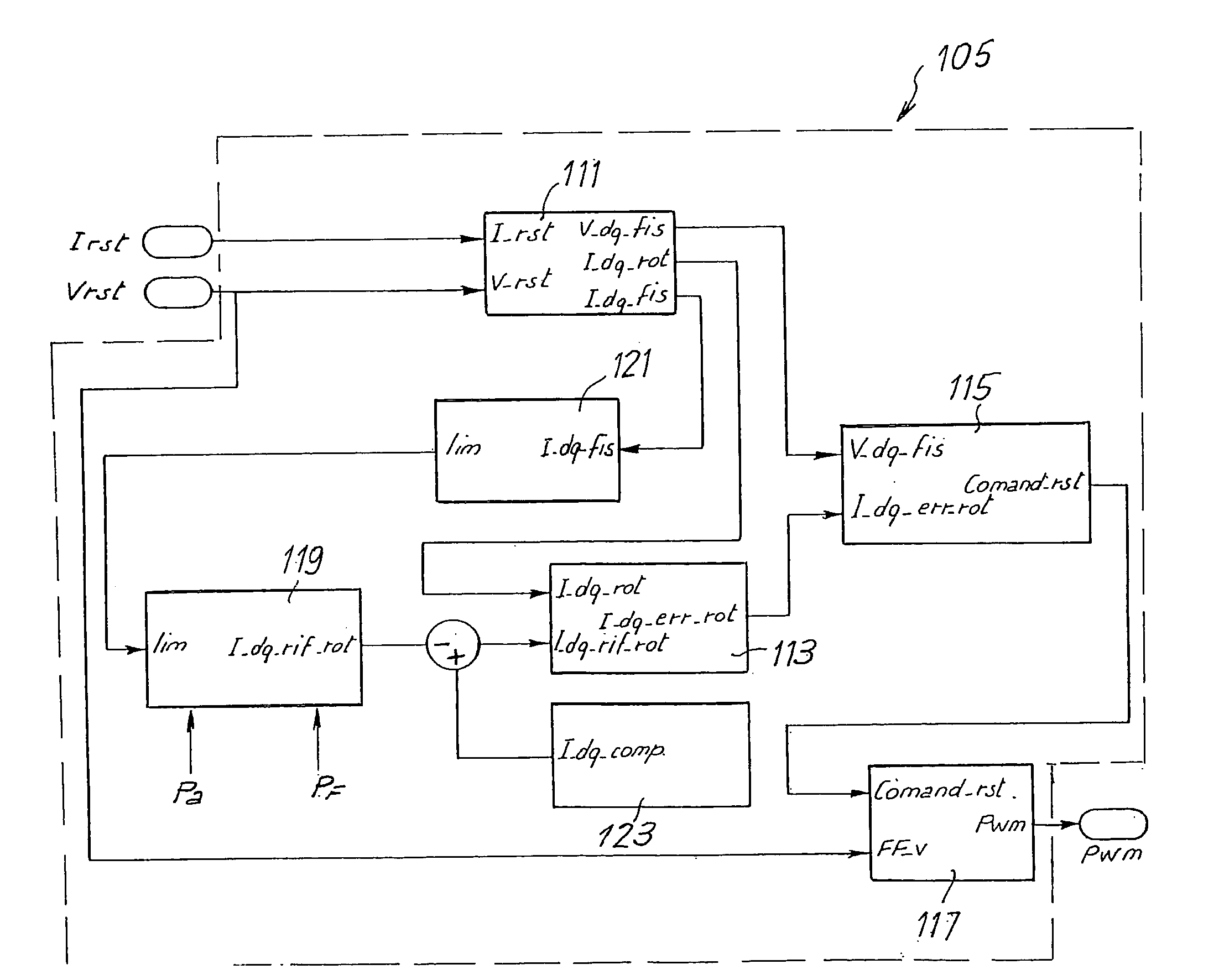
A method of controlling an inverter to includes determining the components of a phasor representing the output current from the inverter in a fixed reference system; determining the components of the current phasor in a reference system rotating at a velocity equal to the velocity of rotation of the phasor representing the grid voltage; and comparing the components of the current phasor in the rotating reference system with a reference, again expressed in the rotating reference system, to determine an error signal, by means of which the inverter is controlled.

Description

CROSS-REFERENCES TO RELATED APPLICATIONS[0001]This application is a Non-Provisional Utility application which claims benefit of co-pending European Patent Application Serial No. EU 05425059.2 filed Feb. 9, 2005, entitled “Method and Device for the Control of a Three-Phase Inverter” which is hereby incorporated by reference.STATEMENT REGARDING FEDERALLY SPONSORED RESEARCH OR DEVELOPMENT[0002]Not ApplicableREFERENCE TO SEQUENCE LISTING OR COMPUTER PROGRAM LISTING APPENDIX[0003]Not ApplicableBACKGROUND OF THE INVENTION[0004]The present invention relates in general to the control of three-phase inverters used to supply electrical power from a generic electrical power source to a three-phase grid, to which a load with known characteristics may be applied. More specifically, the present invention relates to a method and to a device for regulating an inverter in parallel to the grid.[0005]In the use of renewable energies and more generally alternative energies, it is frequently necessary t...

Claims


Application Information

Patent Timeline
Patent Type & Authority Patents(United States)
IPC IPC(8): H02M3/24H02M7/44H02M7/5387
CPCH02M7/53873H02J3/383H02J3/387H02M2007/53876Y02E10/563H02J2300/30H02J2300/24H02J3/381H02J3/44H02M7/53876Y02E10/56
Inventor MARRONI, ETTOREMARTINI, DAVID
Owner MARICI HLDG THE NETHERLANDS BV
Learn More