Pump valve with controlled stroke

a valve and valve body technology, applied in the field of pumps, can solve the problems of inefficient pump operation and/or higher noise level, and achieve the effect of preventing inefficiency and excess nois

Active Publication Date: 2010-07-27
PARKER INTANGIBLES LLC
View PDF13 Cites 7 Cited by
  • Summary
  • Abstract
  • Description
  • Claims
  • Application Information

AI Technical Summary

Benefits of technology

[0004]Therefore, it is an object of the invention to provide a valve assembly in which the stroke of a flexible valve is limited to prevent inefficiency and excess noise.
[0005]It is another object of the invention to provide a valve assembly which prevents overlap of intake and exhaust valves.
[0006]It is another object of the invention to provide a valve assembly having good sealing characteristics without excess travel of the valve elements.
[0008]According to another preferred embodiment of the invention, a valve assembly further includes a third recess formed in the pump chamber; a fourth recess formed in the pump head, the fourth recess cooperating with the third recess to define a second valve compartment including a second valve pocket and an opposed second valve seat; and a flexible second valve element disposed between the third and fourth recesses and adapted to move between a closed position against the second valve seat which prevents fluid flow and an open position away from the second valve seat which permits fluid flow in a second direction. The dimensions of the second valve compartment are selected to limit the movement of the second valve element in the open position.
[0017]According to another preferred embodiment of the invention, the valve assembly further includes a third recess formed in the pump chamber; a fourth recess formed in the pump head, the fourth recess cooperating with the third recess to define a second valve compartment including a second valve pocket and an opposed second valve seat; and a flexible second valve element having a selected second thickness disposed between the third and fourth recesses, and adapted to move between a closed position against the second valve seat which prevents fluid flow and an open position away from the second valve seat which permits fluid flow in a second direction. The dimensions of the second valve compartment are selected to limit the stroke length of the second valve element to less than about 1.6 times the second thickness.

Problems solved by technology

If this valve travel distance is not controlled correctly, the valve can easily travel further than required or could also be over-restricted and not allowed to travel as far as needed.
Either condition results in a pump that runs inefficiently and / or produces higher than desired noise levels.

Method used


Image

  • Pump valve with controlled stroke
  • Pump valve with controlled stroke
  • Pump valve with controlled stroke

Examples


Embodiment Construction

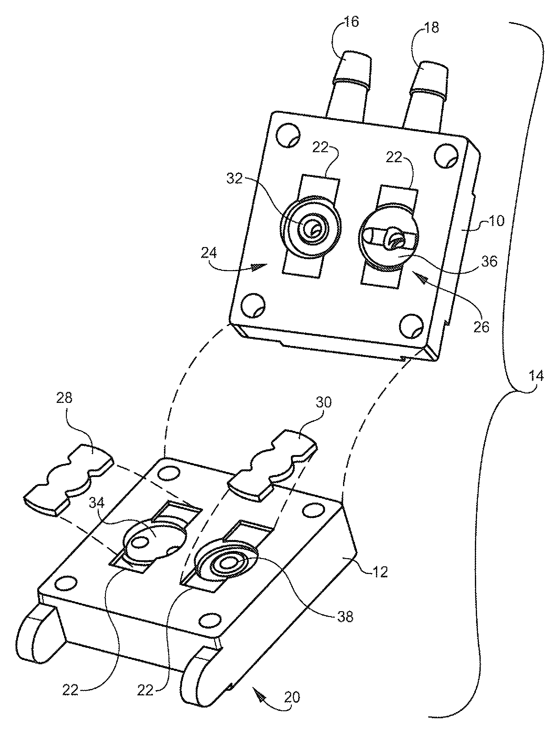
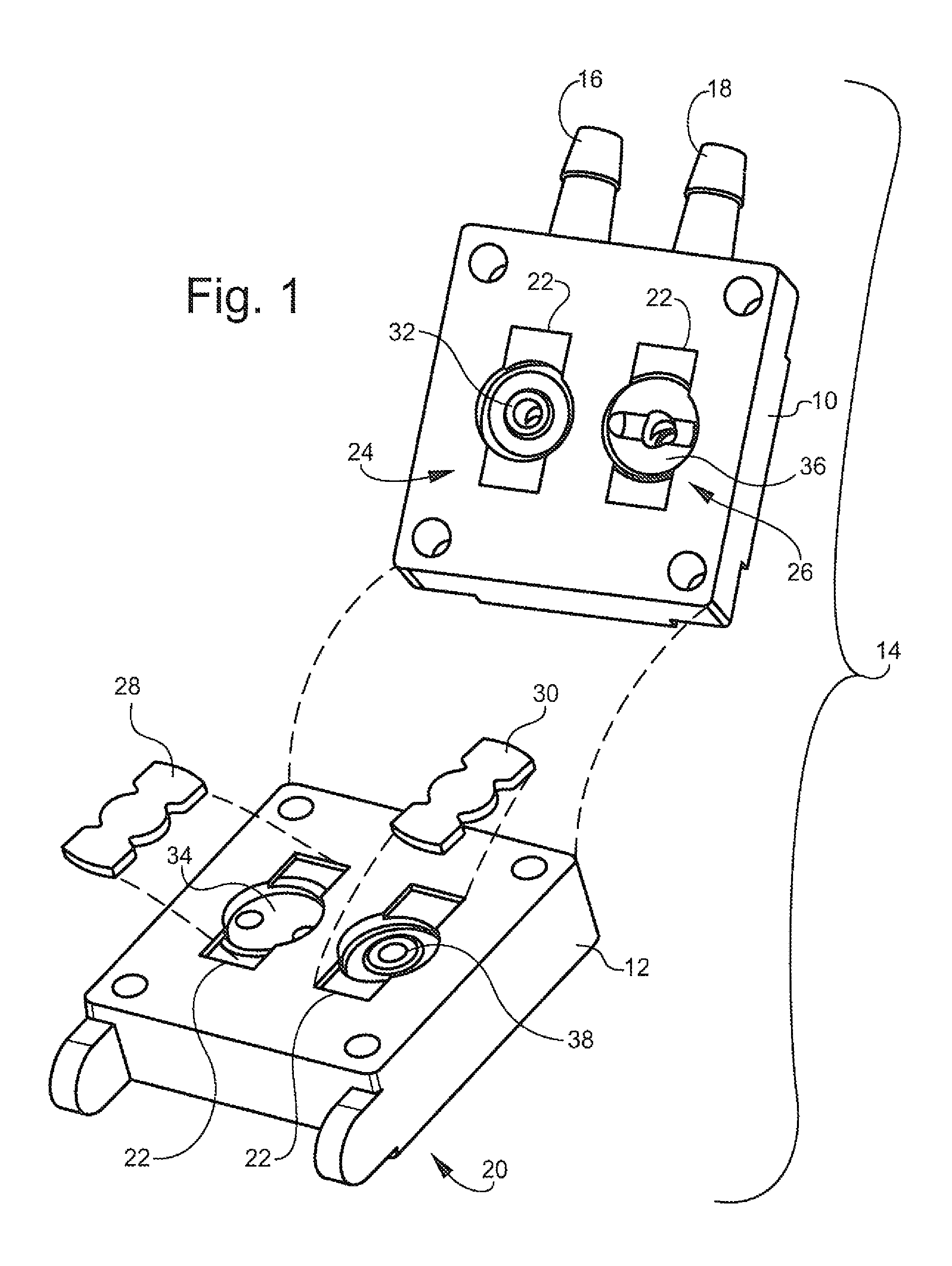
[0028]FIG. 1 illustrates a portion of a prior art diaphragm pump assembly. A head 10 is attached to a chamber 12. The head 10 and the chamber 12 are referred to collectively as a pump head 14. Inlet and outlet connections 16 and 18 extend from the head 10. Each of these connections communicates with a fluid flow path through the pump head 14 and into a diaphragm pump body of a known type (not shown) which is attached to a lower end 20 of the pump head 14. The head 10 and the chamber 12 each have complementary recesses 22 therein. When the head 10 is assembled to the chamber 12, these recesses 22 cooperate to define an inlet valve compartment 24 and an outlet valve compartment 26. Inlet and outlet diaphragm valves 28 and 30 are received in these compartments and are trapped between the head 10 and the chamber 12. The upper part of the inlet valve compartment 24 is defined by an annular, radiused inlet valve seat 32 formed in the head 10. The inlet valve 28 seals against the inlet val...


PUM


Abstract

A valve assembly for a pump includes a pump chamber and a pump head having complementary recesses formed therein which cooperate to define a valve compartment including a pocket and an opposed seat. A flexible valve element is disposed between the recesses and adapted to move between a closed position against the seat which prevents fluid flow and an open position away from the valve seat which permits fluid flow. The dimensions of the valve compartment are selected to limit the movement of the valve element in the open position, which increases the pump efficiency and prevents damage to the valve element and / or valve overlap.

Description

BACKGROUND OF THE INVENTION[0001]This invention relates generally to pumps and more particularly to a check valve for a pump. Many types of pumps use check valves; however for the purpose of describing the present invention diaphragm pumps in particular are considered herein. Typical diaphragm pumps use an elastomeric component as a passive check valve to facilitate the pumping action of the pump. A pump will typically contain two valves, one identified as the inlet valve and the other identified as the outlet valve. During the down-stroke or intake stroke of the pump, the suction action of the diaphragm will pull the inlet valve into an open position and the outlet valve into a closed position thus pulling the media into the pump on the inlet side only. During the up-stroke or exhaust stroke of the pump, the compression action of the diaphragm will push the inlet valve into a closed position and the outlet valve into an open position thus expelling the media on the outlet side only...

Claims


Application Information

Patent Timeline
Patent Type & Authority Patents(United States)
IPC IPC(8): F04B39/10F04B53/10F16K15/14F16K15/16F04BF16K7/17
CPCF04B39/1073F04B39/14F04B53/1047F04B53/1062F04B53/1085F04B53/1087F16K7/17F16K15/144F04B39/10F04B39/104F04B39/1066Y10T137/7887Y10T137/7892
Inventor HARGRAVES, DONALD EDWINCURTIS, DOUGLAS ALLAN
Owner PARKER INTANGIBLES LLC
Why Eureka
Try Eureka