Inter-cervical facet implant with locking screw and method

a technology of facet implants and locking screws, which is applied in the field of interspinous process implants, can solve the problems of reducing the foraminal area, radicular pain, neck pain and muscle weakness,

Inactive Publication Date: 2010-07-27
KYPHON
View PDF390 Cites 121 Cited by
  • Summary
  • Abstract
  • Description
  • Claims
  • Application Information

AI Technical Summary

Problems solved by technology

Spinal stenosis results in a reduction foraminal area (i.e., the available space for the passage of nerves and blood vessels) which compresses the cervical nerve roots and causes radicular pain.
Another symptom of spinal stenosis is myelopathy, which results in neck pain and muscle weakness.
Extension and ipsilateral rotation of the neck further reduces the foraminal area and contributes to pain, nerve root compression, and neural injury.

Method used


Image

  • Inter-cervical facet implant with locking screw and method
  • Inter-cervical facet implant with locking screw and method
  • Inter-cervical facet implant with locking screw and method

Examples


embodiment 500

[0071]FIG. 8 shows a further embodiment 500 of the implant of the invention, wherein the joint insert or inter-facet spacer 510 has a keel 550 on an underside of the joint insert or inter-facet spacer 510. The keel 550 can be made of the same material or materials set forth above. The surfaces of the keel 550 can be roughened in order to promote bone ingrowth to stabilize and fix the implant 500. In other embodiments, the keel 550 can be coated with materials that promote bone growth such as, for example, bone morphogenic protein (“BMP”), or structural materials such as hyaluronic acid “HA,” or other substances which promote growth of bone relative to and into the keel 550.

[0072]The keel 550 can be embedded in the facet bone, to facilitate implant retention. The keel 550 can be placed into a channel in the facet bone. The channel can be pre-cut. Teeth (not shown), preferably positioned posteriorly, also may be formed on the keel 550 for facilitating retention of the implant 500 in t...

embodiment 1000

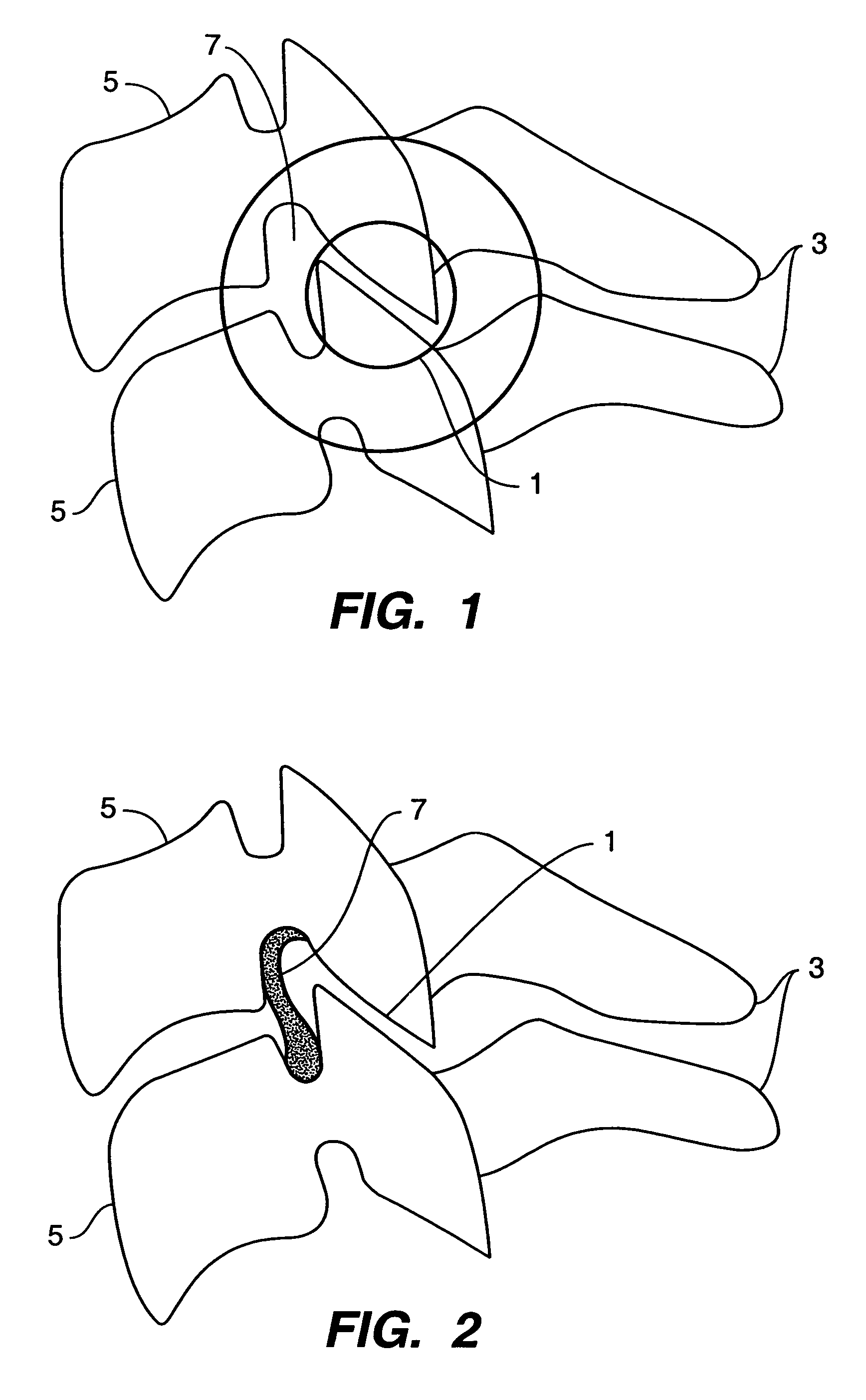
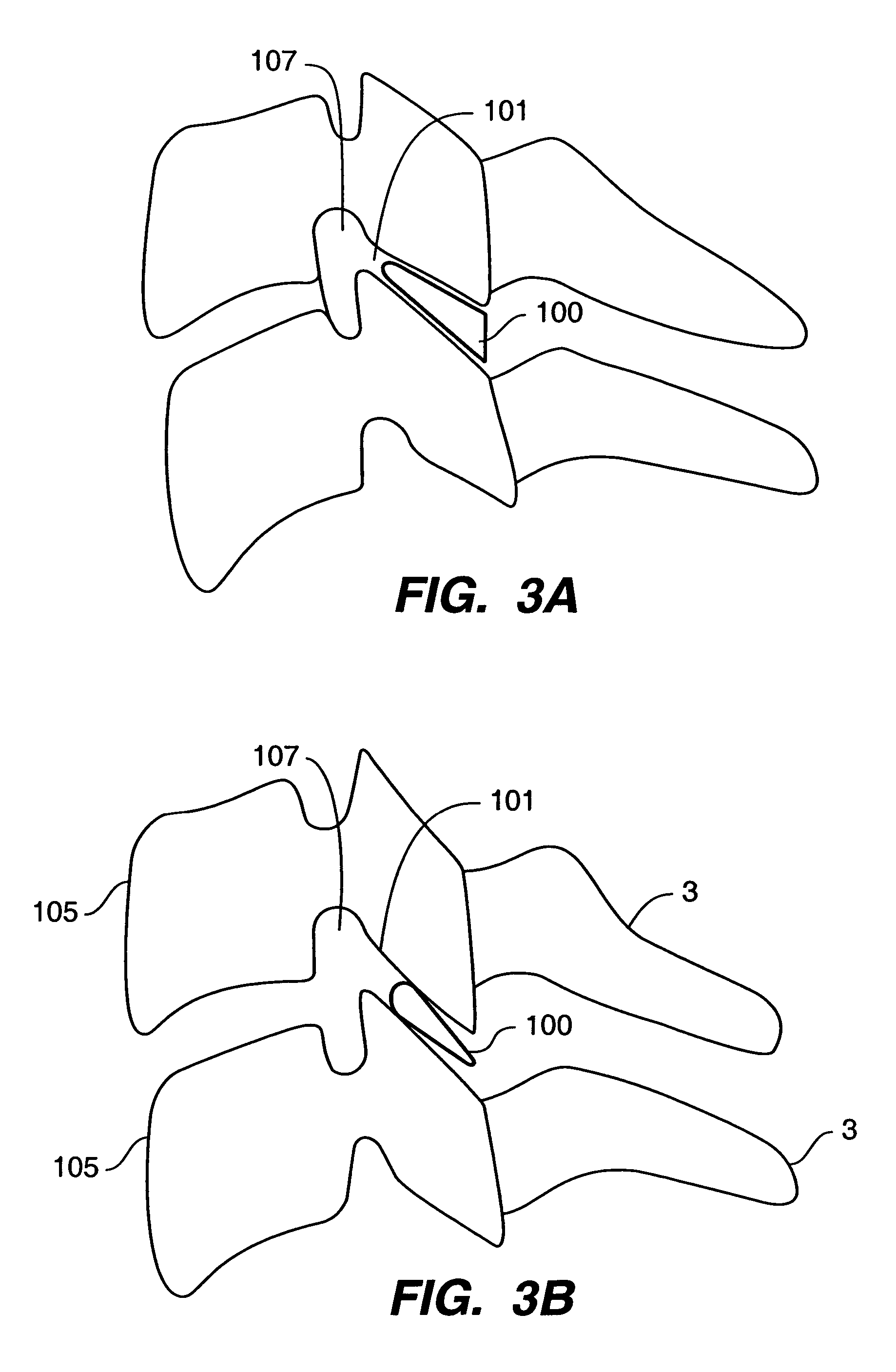
[0077]FIG. 13 depicts yet another embodiment 1000 of the implant of the present invention. In this embodiment 1000, the joint inserts or inter-facet spacers 1010 of two implants 1000 are positioned in a cervical facet joint 1001. As described above, the joint inserts or inter-facet spacers 1010 can be wedge-shaped as needed to restore anatomical curvature of the cervical spine and to distract, or the joint inserts or inter-facet spacers 1010 can be of substantially uniform thickness. The implants 1000 each comprise a joint insert or inter-facet spacer 1010 with an outer surface 1070 that interacts with the bone of the cervical facet joint 1001. On the upper implant 1000, the surface 1070 that interacts with the bone is the upper surface and on the lower implant 1000, the surface 1070 that interacts with the bone is the lower surface. As set forth above, each outer surface 1070 can comprise a bone ingrowth surface 1080 to create a porous surface and thereby promote bone ingrowth and ...

embodiment 1100

[0079]FIG. 14 depicts a further embodiment 1100 of the implant of the present invention. In this embodiment 1100, the joint inserts or inter-facet spacers 1110 of two implants 1100 are inserted into the cervical facet joint 1101. Each of the joint inserts or inter-facet spacers 1110 is continuous with a cervical facet joint extender or facet-extending surface 1192. The bone contacting surfaces 1170 of the joint inserts or inter-facet spacers 1110 are continuous with, and at an angle to, the bone contacting surfaces 1193 of the cervical facet joint extenders 1192, so that the cervical facet joint extenders 1192 conform to the bones of the vertebrae exterior to the cervical facet joint 1101. The conformity of the cervical facet joint extenders 1192 is achieved, for example, by forming the cervical facet joint extenders 1192 so that when the joint inserts or inter-facet spacers 1110 are positioned, the cervical facet joint extenders 1192 curve around the bone outsider the cervical face...


PUM


Abstract

Systems and method in accordance with the embodiments of the present invention can include an implant for positioning within a cervical facet joint for distracting the cervical spine, thereby increasing the area of the canals and openings through which the spinal cord and nerves must pass, and decreasing pressure on the spinal cord and / or nerve roots. The implant can be inserted laterally or posteriorly.

Description

CLAIM OF PRIORITY[0001]This application claims priority to United States Provisional Application, entitled, INTER-CERVICAL FACET IMPLANT AND METHOD filed Dec. 13, 2004, Ser. No. 60 / 635,453, which is incorporated herein by reference.CROSS-REFERENCE TO RELATED APPLICATIONS[0002]This application is related to U.S. patent application Ser. No. 11 / 053,399, entitled INTER-CERVICAL FACET IMPLANT AND METHOD, filed Feb. 8, 2005; U.S. patent application Ser. No. 11 / 053,624, entitled INTER-CERVICAL FACET IMPLANT AND METHOD, filed Feb. 8, 2005; U.S. patent application Ser. No. 11 / 053,735, entitled INTER-CERVICAL FACET IMPLANT AND METHOD, filed Feb. 8, 2005; U.S. patent application Ser. No. 11 / 053,346, entitled INTER-CERVICAL FACET IMPLANT AND METHOD, filed Feb. 8, 2005; and U.S. patent application Ser. No. 11 / 093,689, entitled INTER-CERVICAL FACET IMPLANT AND METHOD FOR PRESERVING THE TISSUES SURROUNDING THE FACET JOINT, filed Mar. 30, 2005 each of which is incorporated herein in full, by refere...

Claims


Application Information

Patent Timeline
Patent Type & Authority Patents(United States)
IPC IPC(8): A61B17/70
CPCA61F2/4405A61B17/562A61B17/7007A61B17/701A61B17/7022A61B17/7028A61B17/7064A61B17/7071A61B17/8042A61B2017/8655
Inventor WINSLOW, CHARLES J.ZUCHERMAN, JAMES F.HSU, KEN Y.MITCHELL, STEVEN T.YERBY, SCOTT A.FLYNN, JOHN J.
Owner KYPHON
Why Eureka
Try Eureka