
Elevator control system

a technology of elevator control and control system, applied in the field of elevator control, can solve the problems of only learning the customer, inability to allocate only one elevator for passengers, and the same destination floor, and achieve the effect of improving the efficiency of the elevator control system

Inactive Publication Date: 2010-08-03
KONE CORP
View PDF22 Cites 22 Cited by
  • Summary
  • Abstract
  • Description
  • Claims
  • Application Information

AI Technical Summary

Benefits of technology

The present invention aims to improve the efficiency of elevator control systems by combining the benefits of traditional collective control and destination control. In one embodiment, a call input system is used that allows for direct destination calls on floors with intensive departing traffic. The system can also identify regular customers and store their most frequent destination floors in a database, which can be used to improve call control. The invention also allows for the granting of personal use functions to regular customers and the denial of access to destination floors to occasional users. Overall, the invention enhances elevator control efficiency by optimizing call input and utilizing customer information.

Problems solved by technology

The problematics consist in determining the most optimal elevator, defined by a desired indicator, for each elevator passenger having entered a call, and controlling the elevators in accordance with the optimization results.
The collective control method has the disadvantage that the system only learns the customer's destination floor after the elevator has already arrived at the customer's original floor of location.
Therefore, it is impossible to allocate only one elevator for passengers wanting a ride to the same destination floor at the same time, because the system knows nothing of the customers' destination floors on the basis of the depressions of up / down buttons.
Due to the destination call device, destination control may be more expensive than traditional collective control.
In such a system it is not possible to enter a traditional up or down call, but the user always has to enter a destination call.
A problem with collective control is that the system is not informed about the customers' destination floors until after the customer has entered the elevator car.
Destination control again involves the problem of higher costs as compared to the collective control system.

Method used


Image

  • Elevator control system
  • Elevator control system
  • Elevator control system

Examples


Embodiment Construction

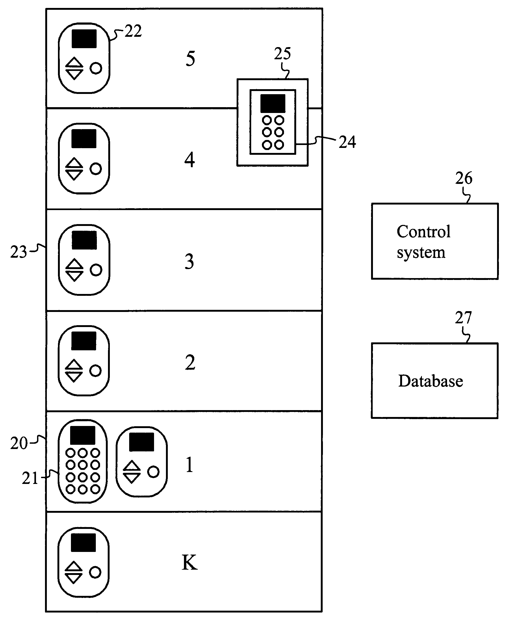
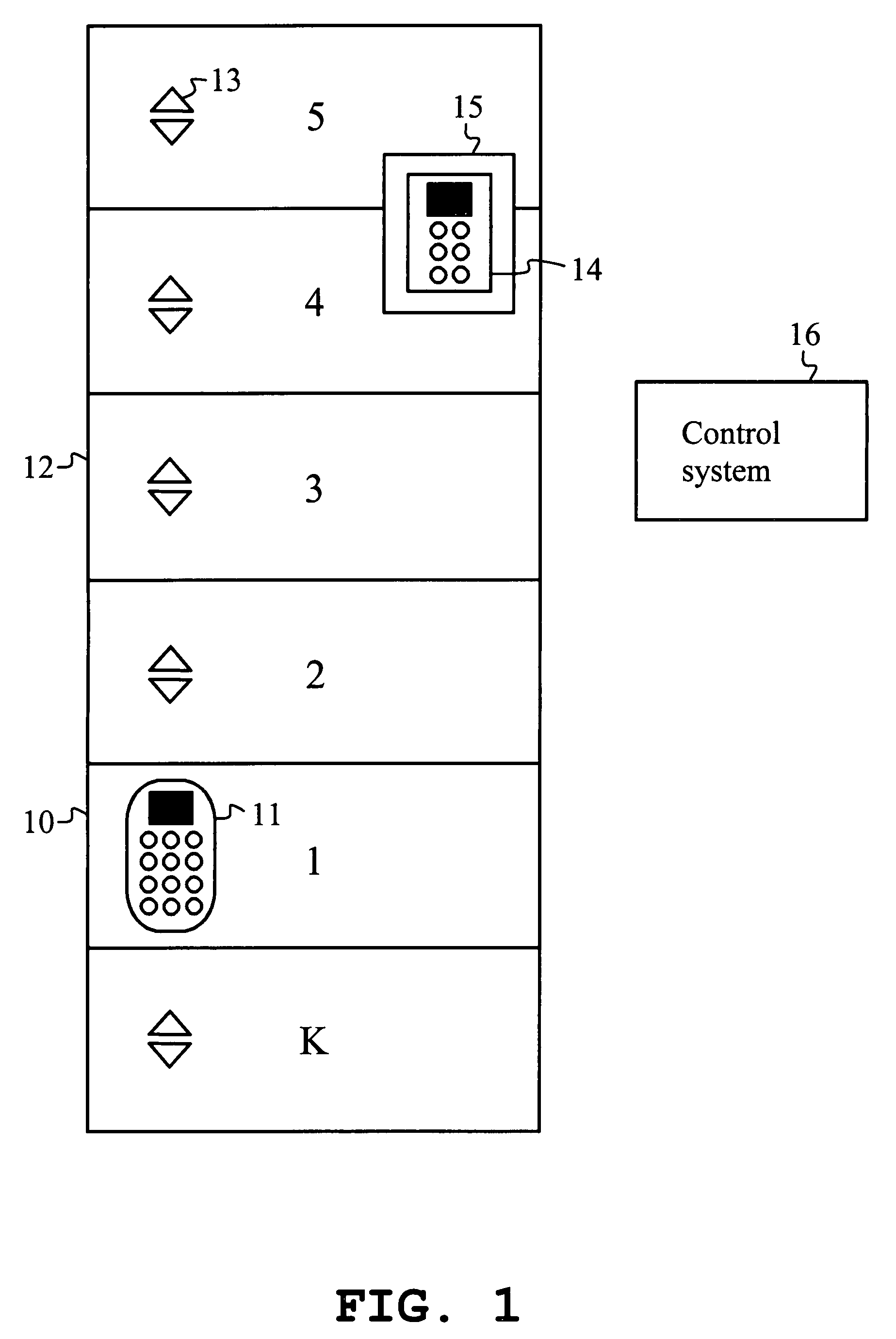
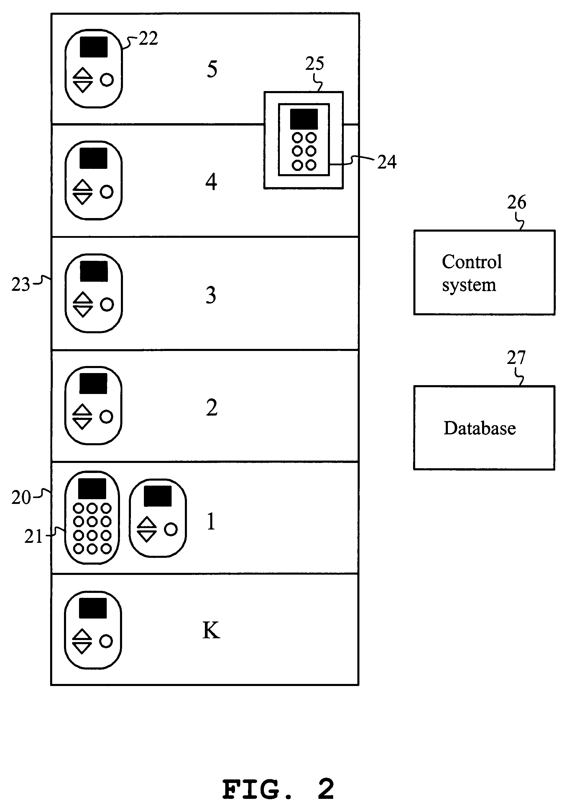
[0018]The method of the present invention for controlling an elevator group combines aspects of the collective control system and the destination call control system. The new method is called here a hybrid-type control system. FIG. 1 presents the call input devices required in the control system, along with different floor types.

[0019]On floors 10 with intensive traffic to other floors of the building, a destination control system is used. Such a floor may typically be e.g. the entrance floor 10 of the building. Passengers going to the same floors can be guided to the same elevator cars, and thus the number of stops can be minimized. Floors where the departing traffic exceeds a desired limit can be designated as floors with intensive traffic 10, and these floors are provided with a so-called complete call panel 11 containing number keys, which is placed near the elevator door. The call panel 11 may naturally be located farther away, e.g. at a distance of 15 m from the elevator door....


PUM


Abstract

For entry of calls in an elevator system, a destination call is entered outside the elevator car if the starting floor is a floor with intensive departing traffic. On other floors, a collective-control up or down call is entered traditionally and then a destination call in the elevator car. An identified regular customer may be allowed to select and confirm a destination floor from among one or more preprogrammed alternatives. Destination preprogrammed floors most frequently used are stored, the starting floor being fixed. Preprogrammed floors can be set for several different starting floors separately. For occasional customers system or regular customers going to floors other than preprogrammed floors, a call is entered as a destination call in the elevator lobby on floors with intensive departing traffic and as an up or down call according to collective control in the elevator lobby and on other floors.

Description

[0001]This application is a Continuation of copending PCT International Application No. PCT / FI2005 / 000536 filed on Dec. 19, 2005, which designated the United States, and on which priority is claimed under 35 U.S.C. §120.FIELD OF THE INVENTION[0002]The present invention relates to elevator control effected on the basis of calls entered in an elevator system.BACKGROUND OF THE INVENTION[0003]In the operation of an elevator system, it is essential to receive and process the call data entered by passengers. The problematics consist in determining the most optimal elevator, defined by a desired indicator, for each elevator passenger having entered a call, and controlling the elevators in accordance with the optimization results. In an elevator system, a customer arriving to the elevator calls an elevator to the floor where he / she is currently located by pressing the button of a call device near the elevator door. The commonest solution for implementing the call device is to provide up and...

Claims


Application Information

Patent Timeline
Patent Type & Authority Patents(United States)
IPC IPC(8): B66B1/34B66B1/20B66B1/46
CPCB66B1/20B66B1/468B66B2201/4615B66B2201/4623B66B2201/463B66B2201/4661B66B2201/4676
Inventor MAKELA, MARJUKKASIPILA, TOMI
Owner KONE CORP
Learn More