Wall mounting structure for a flat panel display

a flat panel display and mounting structure technology, applied in the direction of candle holders, rigid containers, lightening support devices, etc., can solve the problem of almost impossible mounting brackets for mounting brackets, and achieve the effect of convenient and convenient manner

Active Publication Date: 2010-08-03
LG ELECTRONICS INC
View PDF30 Cites 24 Cited by
  • Summary
  • Abstract
  • Description
  • Claims
  • Application Information

AI Technical Summary

Benefits of technology

[0013]It is an object of the present invention to provide a wall mounting structure for a flat panel display, by which a user can mount the flat panel display on a mounting bracket on a wall in an easy and convenient manner without separating a stand assembly from a display screen of the flat panel display.

Problems solved by technology

If the opening is larger than a corresponding VESA (Video Electronics Standard Association) standard for wall mounting, it is nearly impossible to hang the stand assembly on the mounting bracket due to the opening.

Method used


Image

  • Wall mounting structure for a flat panel display
  • Wall mounting structure for a flat panel display
  • Wall mounting structure for a flat panel display

Examples


second embodiment

[0033]In the present invention, the rotatable holding arm 12 may further include an arm-holding means 16 for retaining the rotatable holding arm 12 at a particular position, for example a seated position or a rotated position, within a range in which the rotatable holding arm 12 rotates in a lower part of the base 4 (see FIGS. 6 through 8).

[0034]The arm-holding means 16 includes an elastic member space 14aa, an elastic member 17, and at least one holding groove 12b or 12b′. The elastic member space 14aa is formed within the arm-seating recess 14a of the base 4. The elastic member 17 is releasably seated in the elastic member space 14aa and has at least one holding protuberance 17a formed at one side of the elastic member 17. The at least one holding groove 12b or 12b′ is formed at a portion of the rotatable holding arm 12 corresponding to the holding protuberance 17a of the elastic member 17 (see FIG. 8).

[0035]One of the holding grooves 12b and 12b′ is formed at a portion of the rot...

first embodiment

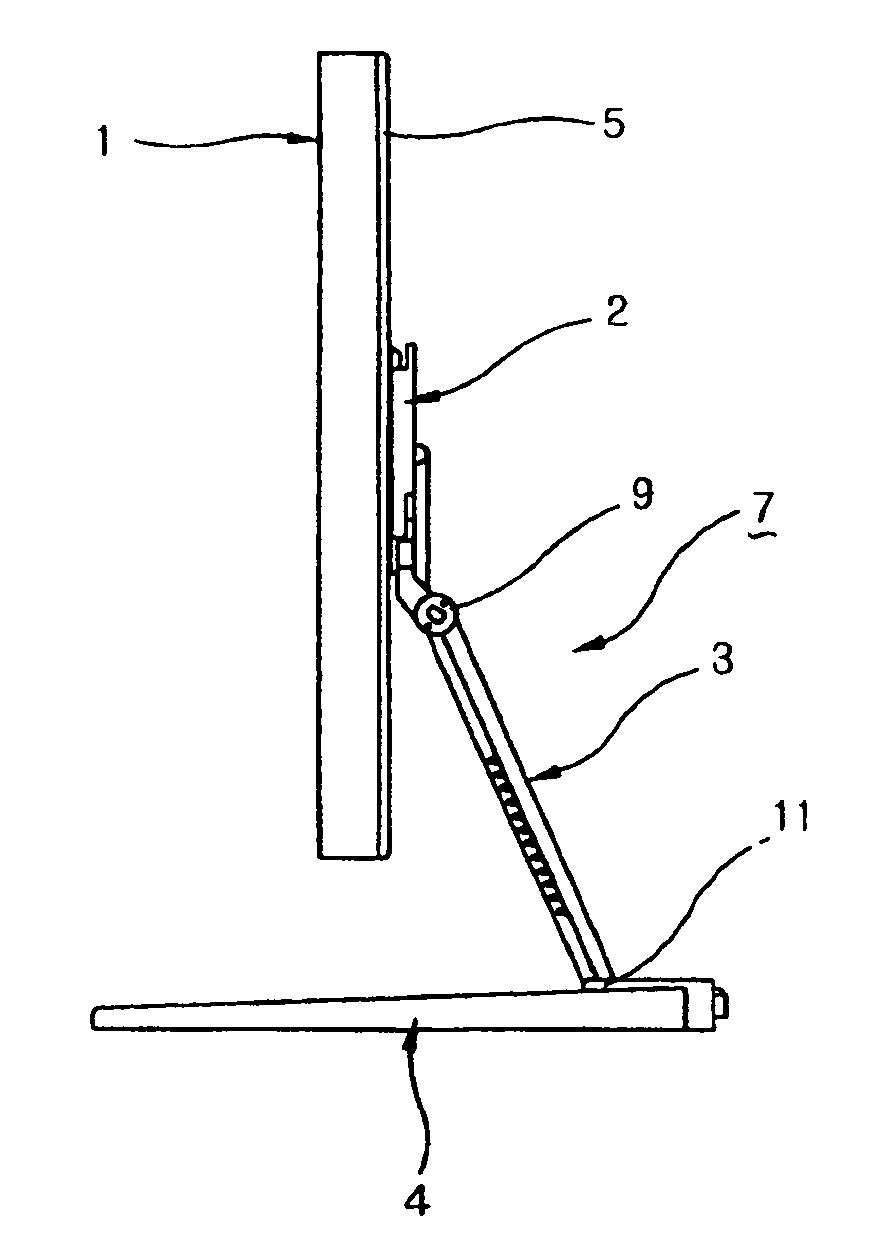
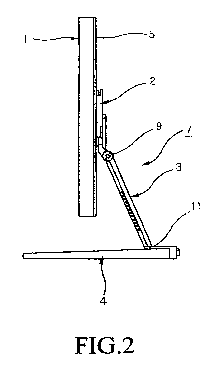
[0038]A process and an operation for assembling a flat panel display employing the wall mounting structure according to the present invention will now be described with reference to FIGS. 2 through 5. In order to fold a flat panel display standing upright on a table and then hang the monitor on a wall, a user first pushes the display screen 1 around the first hinge 9 toward the stand 3 to fold the display screen 1 and the stand 3 together. Then, the user pushes the display screen 1 and the stand 3 toward the base 4 around the second hinge 11 (see FIGS. 2 and 3).

[0039]Then, the user picks up the flat panel display and aligns the monitor with mounting brackets (not shown) fixed to a wall. In this state, the user rotates the rotatable holding arms 12 of the rotatable mounting members 10 provided at the lower part of the base 4 of the flat panel display outward from the arm-seating recesses 14a and then fittingly inserts the front end of the rotatable holding arms 12 into corresponding ...


PUM


Abstract

A wall mounting structure includes a display screen, a stand, and a base. The stand has an upper end connected to a rear surface of the display screen via a first hinge so as to enable the display screen to be rotated forward and backward. The base is fixed to a lower end of the stand and includes at least two rotatable mounting members formed on a lower part of the base. The rotatable mounting members enable the base to be detachably mounted on mounting brackets of a wall. The wall mounting structure enables a user to not only use a flat panel display on a table, but also to hang the flat panel display on mounting brackets fixed to a wall in an easy and simple manner without disassembling the display screen and the stand assembly from each other.

Description

[0001]This nonprovisional application claims priority under 35 U.S.C. §119(a) on Patent Application No. 10-2004-056831 filed in Korea on Jul. 21, 2004, and Patent Application No. 10-2004-064610 filed in Korea on Aug. 17, 2004, each of which are herein incorporated by reference.BACKGROUND OF THE INVENTION[0002]1. Field of the Invention[0003]The present invention relates generally to a wall mounting structure for a flat panel display, such as an LCD monitor or LCD television. More particularly, the present invention relates to a wall mounting structure for a flat panel display by which a user can mount the flat panel display on a mounting bracket on a wall by means of at least two rotatable mounting members arranged at a lower surface of a base of a stand assembly of the flat panel display in an easy and convenient manner without separating the stand assembly from a display screen of the flat panel display.[0004]2. Description of the Related Art[0005]As shown in FIG. 1, a typical flat...

Claims


Application Information

Patent Timeline
Patent Type & Authority Patents(United States)
IPC IPC(8): A47B91/00A47G29/00B65D19/00
CPCF16M11/10F16M13/02F16M2200/024Y10S248/919Y10S248/921Y10S248/922Y10S248/917Y10S248/92
Inventor CHOI, CHANG WOOBAEK, JIN UK
Owner LG ELECTRONICS INC
Why Eureka
Try Eureka