Transpiration cooled turbine airfoil

a technology of turbine airfoil and turbine blade, which is applied in the direction of liquid fuel engines, marine propulsion, vessel construction, etc., can solve the problems of airfoil increasing, refractory coating made of a very expensive material, and limited diameter of film cooling holes

Inactive Publication Date: 2010-08-03
FLORIDA TURBINE TECH
View PDF19 Cites 59 Cited by
  • Summary
  • Abstract
  • Description
  • Claims
  • Application Information

AI Technical Summary

Benefits of technology

[0011]The present invention is a turbine airfoil with a refractory coating applied to the surface in which the coating includes small diameter cooling holes formed therein. The cooling holes are formed by placing a module of a leachable ceramic material into trenches already formed within the surface of the airfoil substrate. The module includes an array of trusses extending chordwise and spanwise, each truss having a plurality of hole forming extensions to form the cooling holes. The module is placed within the trenches formed on the blade substrate, a refractory coating is applied over the module, and the module is leached away leaving the cooling holes and the diffusion openings formed within the refractory coating.

Problems solved by technology

These film cooling holes are limited to the diameter because of the drilling process.
As the TBC gets thicker, the thermal stresses developed in the TBC will tend to cause spalling.
The refractory coating is made of a material that is very expensive.
As the turbine inlet temperature increases, the cooling flow demand for cooling the airfoil increases as well, and as a result the turbine efficiency is reduced.

Method used


Image

  • Transpiration cooled turbine airfoil
  • Transpiration cooled turbine airfoil
  • Transpiration cooled turbine airfoil

Examples


Embodiment Construction

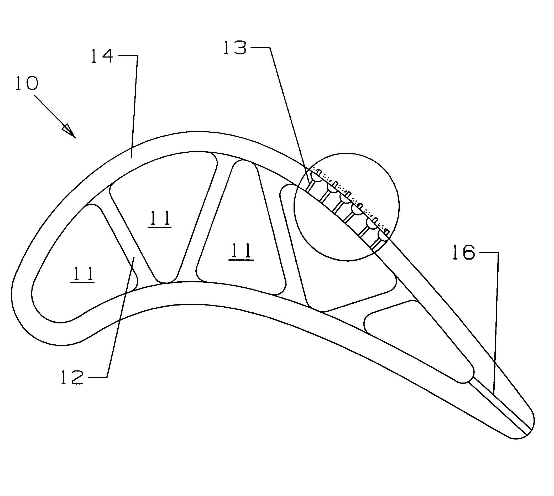
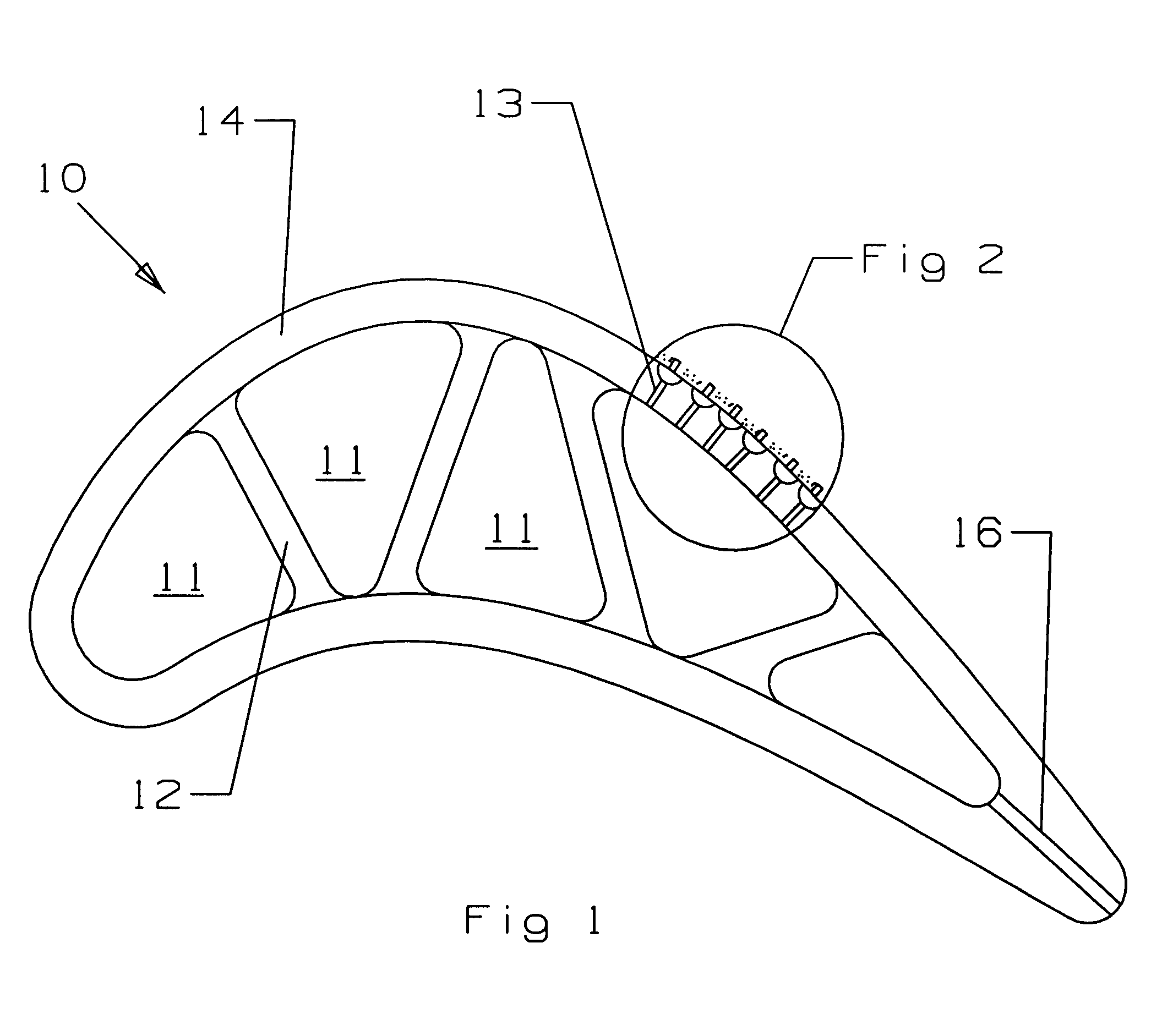
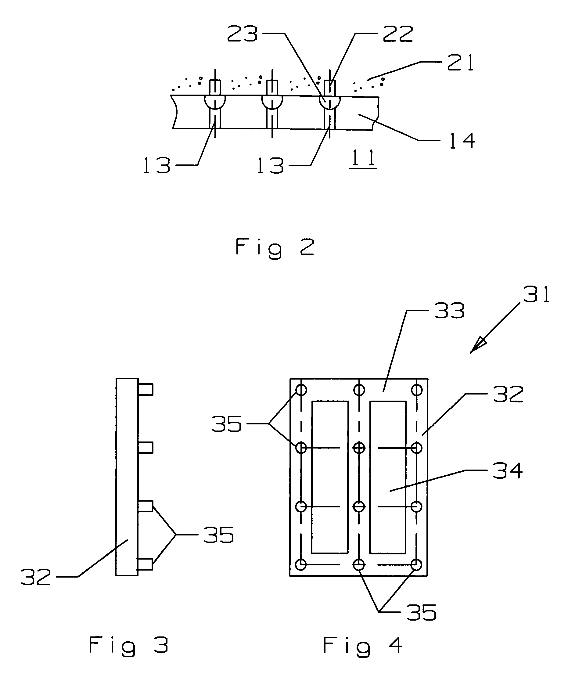
[0016]The present invention is a turbine airfoil, such as a rotor blade or a stator vane, used in a gas turbine engine, in which the turbine airfoil includes a thick refractory coating to provide protection form a higher external gas flow temperature than would a typical ceramic TBC used on the airfoil. The airfoil 10 in the present invention is shown in FIG. 1 and has a leading edge and a trailing edge, and a pressure side and a suction side. Internal cooling air supply channels 11 are formed within the airfoil walls and are separated by ribs 12 that also reinforce the airfoil walls. Exit cooling holes 16 are located in the trailing edge of the blade 10 and discharge cooling air from the downstream channel of the blade. Cooling holes 13 are formed in the main wall or substrate 14 of the blade and connect the internal cooling air supply channels to the cooling holes of the present invention best described in FIG. 2.

[0017]FIG. 2 shows the details of the small cooling holes formed in ...


PUM


Abstract

A turbine airfoil or a substrate exposed to a high temperature environment having a plurality of modular formed cooling circuits with diffusion chambers and cooling holes for each module. Each module includes diffusion chambers and transpiration cooling holes and is placed on the airfoil substrate and a refractory material is formed over the modules. The modules are then leached away leaving the diffusion chambers and cooling holes formed between the substrate and the refractory coating.

Description

BACKGROUND OF THE INVENTIONField of the Invention[0001]The present invention relates generally to fluid reaction surfaces, and more specifically to a turbine airfoil with film cooling holes.[0002]Description of the Related Art including information disclosed under 37 CFR 1.97 and 1.98[0003]A gas turbine engine includes a turbine section that has a plurality of stages of stator vanes and rotor blades reacting to a high temperature gas flow passing through the turbine to convert the chemical energy from combustion into mechanical energy by rotating the turbine shaft. The efficiency of the turbine, and therefore of the engine, can be increased by increasing the hot gas flow that enters the turbine.[0004]To allow for higher turbine entrance temperatures, the upper stage vanes and blades are made from exotic nickel alloys that can withstand very high temperatures and have complex internal cooling air passages to provide cooling to these airfoils. A thermal barrier coating (TBC) is also a...

Claims


Application Information

Patent Timeline
Patent Type & Authority Patents(United States)
IPC IPC(8): F01D5/08
CPCF01D5/186F01D5/288F05D2260/203
Inventor LIANG, GEORGE
Owner FLORIDA TURBINE TECH
Why Eureka
Try Eureka