Particle collector for gas turbine engine

a gas turbine engine and particle collector technology, which is applied in the direction of combustion-air/fuel-air treatment, separation process, filtration separation, etc., can solve the problems of air passing through the gas turbine engine is often subject to high heat, dirt and other impurities can block those small passages

Inactive Publication Date: 2010-08-10
RTX CORP
View PDF12 Cites 32 Cited by
  • Summary
  • Abstract
  • Description
  • Claims
  • Application Information

AI Technical Summary

Problems solved by technology

Numerous components within the gas turbine engine are subject to high levels of heat during operation.
The air passing through a gas turbine engine is often subjected to dirt and other impurities.
The cooling of the components is through relatively small passages, and the dirt and impurities can clog those small passages.
However, these honeycombed materials have not been placed in the cooling air flow such as mentioned above.

Method used


Image

  • Particle collector for gas turbine engine
  • Particle collector for gas turbine engine
  • Particle collector for gas turbine engine

Examples


Embodiment Construction

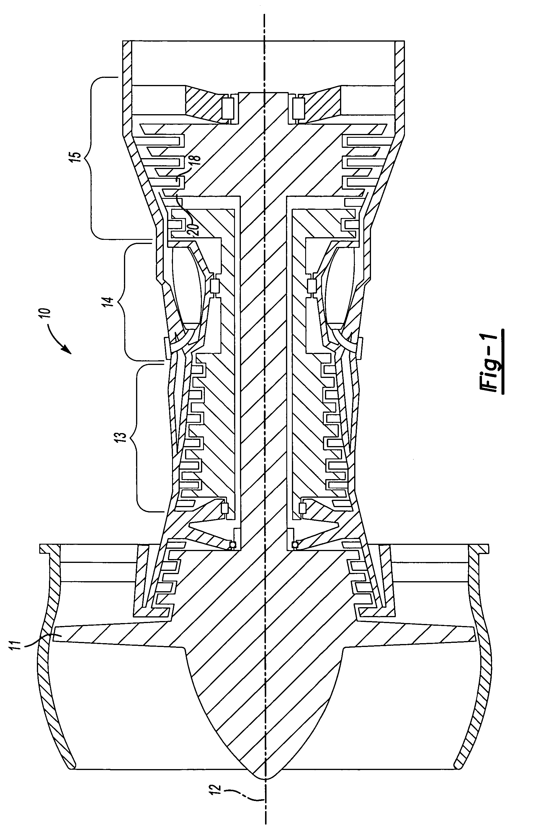
[0018]FIG. 1 shows a gas turbine engine 10. As known, a fan section 11 moves air and rotates about an axial center line 12. A compressor section 13, a combustion section 14, and a turbine section 15 are also centered on the axial center line 12. FIG. 1 is a highly schematic view, however, it does show the main components of the gas turbine engine. Further, while a particular type of gas turbine engine is illustrated in this figure, it should be understood that the present invention extends to other types of gas turbine engines.

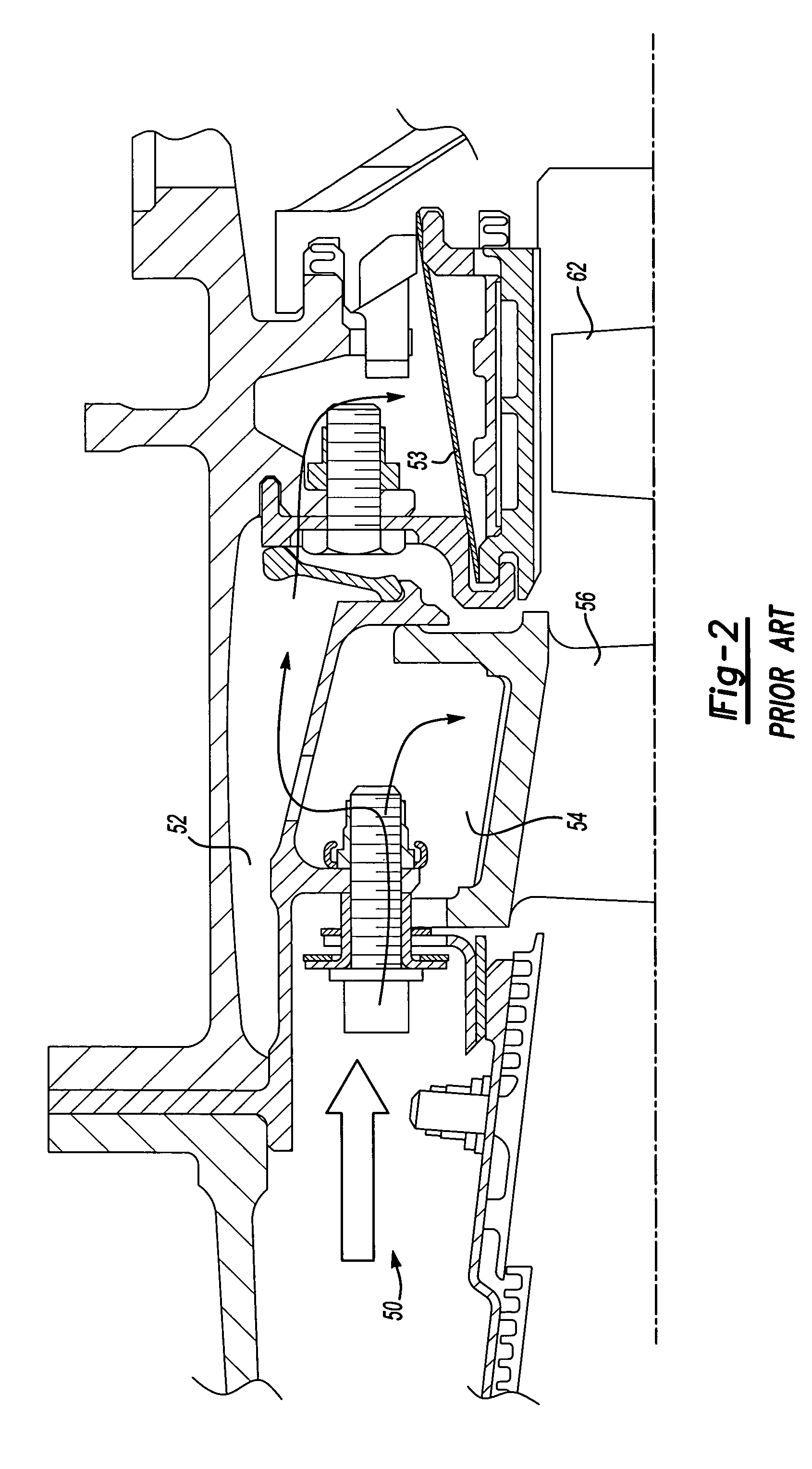
[0019]FIG. 2 shows a detail of a cooling air flow 50 which may pass radially outwardly through an outer cooling air path 52 to a blade outer air seal 53. As is known, the blade outer air seal 53 is positioned radially outwardly of a rotating turbine blade 62. An inner air flow path passes cooling air to a stationary vane 56 and to blade 62.

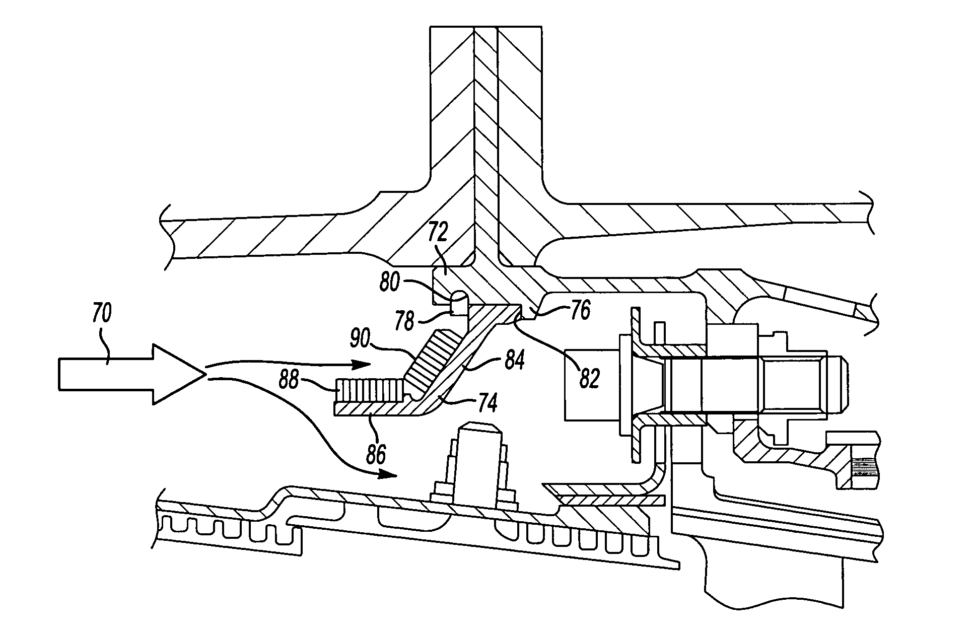
[0020]FIG. 3 shows an inner cooling air flow 60 passing cooling air to an interior passage within a stationary turbine van...


PUM

PropertyMeasurementUnit
shapeaaaaaaaaaa
cross-sectional areaaaaaaaaaaa
honeycomb shapeaaaaaaaaaa

Abstract

A material having a plurality of impurity collection spaces has an outer face facing into a cooling air flow stream for a gas turbine engine component. Impurities such as sand or dirt will collect in the plurality of spaces. In a disclosed embodiment, a honeycombed material is utilized. The material may have a surface that will sit with at least a component parallel to an axial centerline of a gas turbine engine that is to receive the collection material. The material surface may also have a component which is generally perpendicular to the axial centerline. The material may be placed in a gas turbine engine upstream of the turbine section, and downstream of the combustion section. Moreover, the collection material may be placed such that there is cleaner air flow radially inwardly of the collection material, and heavier dirt-laden air passing along the collection material such that impurities can be collected.

Description

BACKGROUND OF THE INVENTION[0001]This application relates to the inclusion of a material into air flow streams in a gas turbine engine, wherein the material has a plurality of collection zones for collecting impurities such as dirt or sand.[0002]Gas turbine engines are provided with a number of functional sections, including a fan section, a compressor section, a combustion section, and a turbine section. Air and fuel are combusted in the combustion section. The products of the combustion move downstream, and pass over a series of turbine rotors, driving the rotors to provide power.[0003]Numerous components within the gas turbine engine are subject to high levels of heat during operation. As an example, a turbine rotor will have a plurality of turbine blades that are driven by high temperature products of combustion to rotate and create the power. Cooling fluid, and typically air, is passed within a body of the turbine blades, seals, and vanes to cool the components.[0004]The air pa...

Claims


Application Information

Patent Timeline
Patent Type & Authority Patents(United States)
IPC IPC(8): F02G3/00
CPCF01D25/32F02C7/05F05D2260/607F05D2260/20
Inventor ALVANOS, IOANNISANDREWS, BERNARD A.CHARBONNEAU, ROBERT A.THOLEN, SUSAN M.DABBS, THURMAN CARLOBRUSKOTTER, MICHAEL J.
Owner RTX CORP
Why Eureka
Try Eureka