Printing apparatus and printing method

a printing apparatus and printing method technology, applied in printing, other printing apparatus, thin material processing, etc., can solve the problems of affecting the printing paper smudge, the probability of ink droplets stalling is enhanced, and the ink droplet ejection is liable to be affected, so as to prevent the ejection of static electricity and eliminate the effect of static electricity generated

Inactive Publication Date: 2010-08-10
SEIKO EPSON CORP
View PDF18 Cites 6 Cited by
  • Summary
  • Abstract
  • Description
  • Claims
  • Application Information

AI Technical Summary

Benefits of technology

[0016]a static electricity eliminating mechanism for eliminating static electricity generated on the printing paper by a conductive member that is arranged in a position to which the ink droplet is ejected from the nozzle or an upstream side of such position on a path through which the printing paper passes.
[0050]According to this printing method, the ink droplet is ejected from the nozzle after the charged charge is eliminated from the printing paper. Therefore, this method is particularly effective in the case of the unframed printing because the ink droplet ejected to the printing paper can be prevented from being adsorbed in the unintended position and also the printing paper can be prevented from being smudged by the micro ink droplet.

Problems solved by technology

The ejection of the ink is liable to be affected by the static electricity generated by the friction between members in the printing apparatus whenever an amount of ink is reduced in this way.
However, the probability of the ink droplets stalling is enhanced since a distance to the ink absorbing material is longer than a distance to the printing paper.
As a result, such a problem exists that the smudge of the printing paper is prone to occur.
Thus, such problems arise that the ink emitted from the nozzles corresponding to portions except the concerned “line” becomes the foregoing micro ink droplets and that such ink droplets stick to the back surface of the printing paper, for example, to smudge the printing paper.
In such case, such a problem also exists that the smudge of the printing paper is caused, like the above case.

Method used


Image

  • Printing apparatus and printing method
  • Printing apparatus and printing method
  • Printing apparatus and printing method

Examples


first embodiment

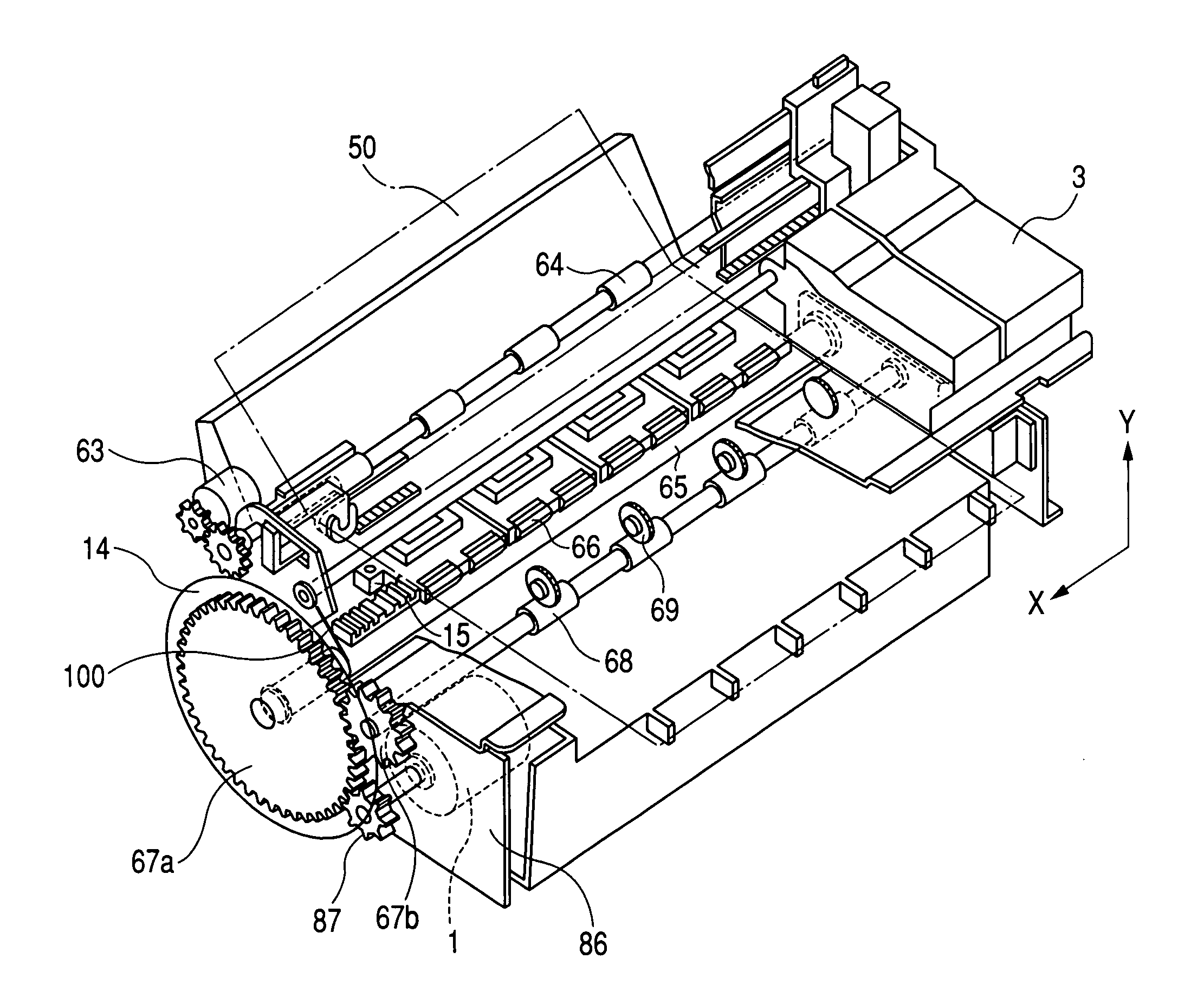
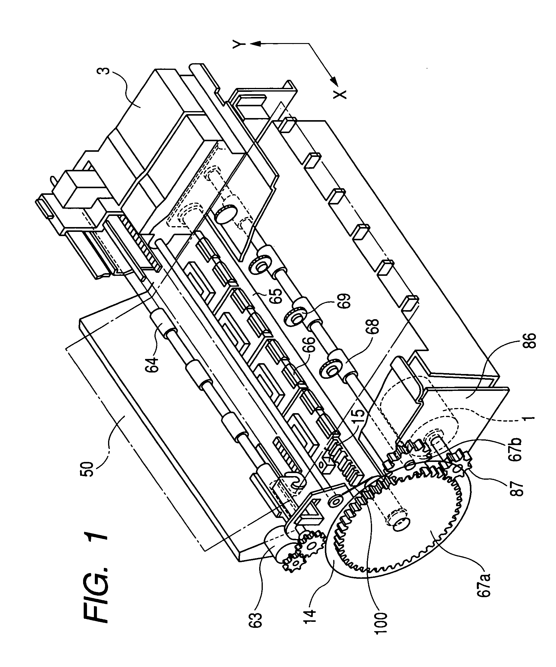
[0072]FIG. 1 is a view showing a configurative example of a printing apparatus according to the present invention.

[0073]As shown in this Figure, the printing apparatus according to the first embodiment of the present invention includes a paper feed motor 1, a carriage 3, an encoder 14, a sensor 15, a paper feed motor 63, a paper feed roller 64, a paper feed roller 65, an idle roller 66, gears 67a, 67b, a paper discharge roller 68, a knurled roller 69, a chassis 86, a gear 87, and an earthing spring member 100.

[0074]Here, the paper feed motor 1 is fixed to the chassis 86, and rotated in response to a control signal from a not-shown control portion to rotate the paper feed roller 65 via the gears 87, 67a and rotate the paper discharge roller 68 via the gears 87, 67b.

[0075]The carriage 3 is reciprocally moved under control of a not-shown carriage motor in the direction (main scanning direction) intersecting orthogonally with the direction (feeding direction) along which a printing pap...

second embodiment

[0207]Next, the present invention will be explained hereunder.

[0208]FIG. 12 is a view showing a configuration of a printing apparatus according to a second embodiment of the present invention.

[0209]In this Figure, the identical reference symbols are affixed to the portions corresponding to the case in FIG. 1 and their explanation will be omitted herein.

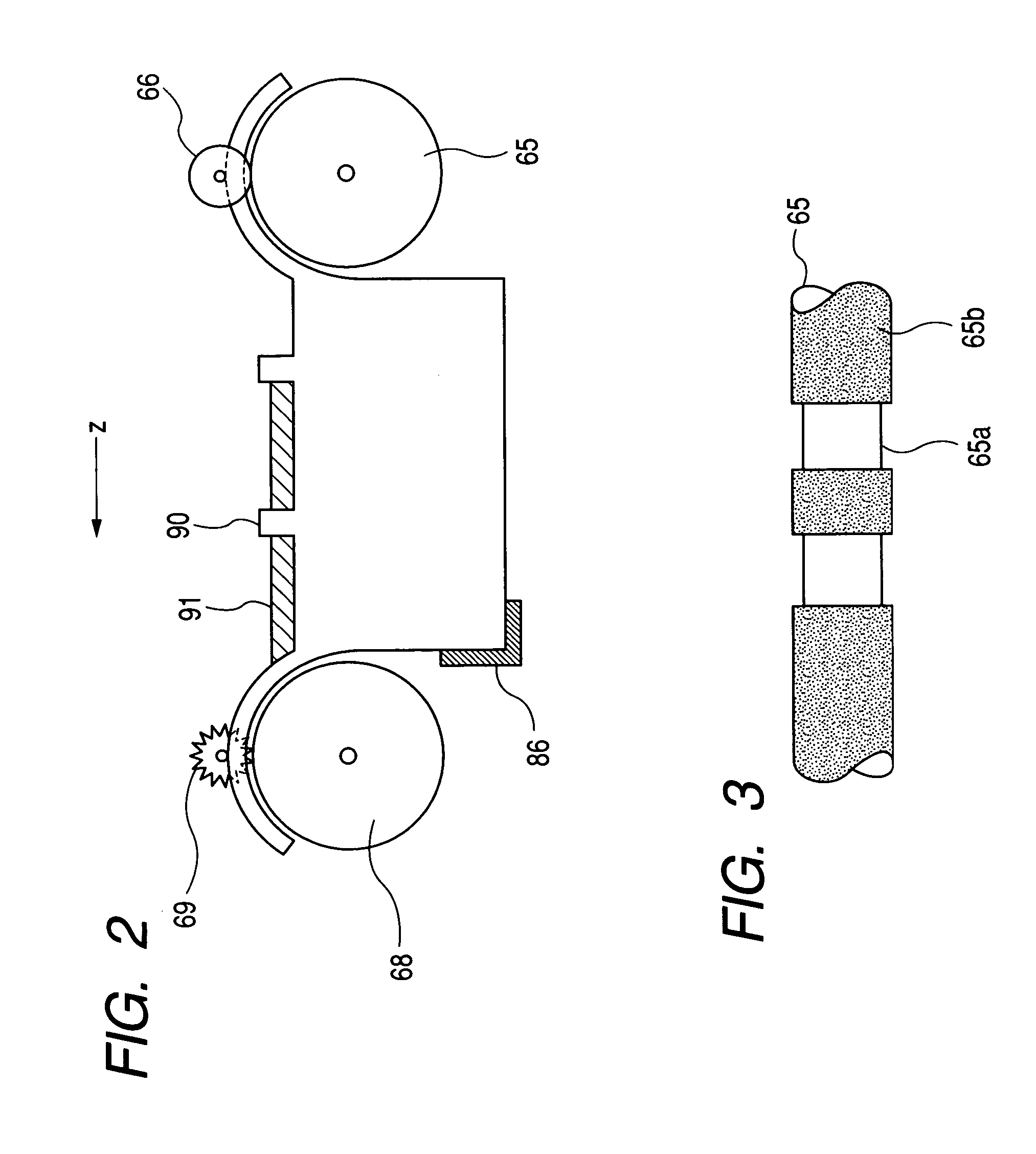
[0210]In the second embodiment of the present invention, in contrast to the case in FIG. 1, the paper feed roller 65 is replaced with a ordinary paper feed roller 93 without the strip-off area 65a, and also the earthing spring member 100 is removed.

[0211]In addition, a copper foil 92 is provided newly to the convex portion of the platen 90, and is earthed to the chassis 86 by a conductive wire 95 described later.

[0212]FIG. 13 is a schematic sectional view taken when the printing apparatus shown in FIG. 12 is cut along a plane perpendicular to the X-direction and viewed from the X-direction. In this Figure, the identical reference symb...


PUM


Abstract

A printing apparatus is provided. The printing apparatus forms a dot in a desired position of a printing sheet by ejecting an ink droplet from a nozzle. A static electricity eliminating mechanism eliminates static electricity generated on the printing sheet by a conductive portion that is arranged in a position to which the ink droplet is ejected from the nozzle or an upstream side of such position on a path through which the printing sheet passes. The conductive portion is formed in at least one of a sheet feed roller and an idle roller that carry the printing sheet. The sheet feed roller or the idle roller is formed by coating a predetermined insulating coating on a surface of a conductive rod-shaped member. The conductive portion is formed by stripping off a part of the coating on the sheet feed roller or the idle roller.

Description

TECHNICAL FIELD[0001]The present invention relates to a printing apparatus and a printing method.BACKGROUND ART[0002]In the ink-jet printing apparatus, dots are formed in desired positions of the printing paper by ejecting the ink from the nozzle by virtue of the pressure generated by the distortion of the piezoelectric element or the pressure generated by the bubble, and thus characters, figures, etc. are printed on the printing paper.[0003]Meanwhile, in order to improve the resolution of the printed image, recently finer dots are formed by reducing an amount of ink droplets ejected from the nozzle in one ejection operation.[0004]The ejection of the ink is liable to be affected by the static electricity generated by the friction between members in the printing apparatus whenever an amount of ink is reduced in this way. Therefore, a method of providing a static electricity eliminating unit was proposed.[0005]In this case, the ink droplets sometimes stall in the middle of the flight ...

Claims


Application Information

Patent Timeline
Patent Type & Authority Patents(United States)
IPC IPC(8): B41J2/17B41J2/01B41J2/18B41J2/185B41J11/00B41J13/00B41J13/02B41J13/076B65H5/00B65H5/06
CPCB41J11/0015B41J11/0065B41J13/02B41J13/076
Inventor ARAYA, MIDORIHABA, KEISUKEWADA, HAJIMEKATAGIRI, NARUHIKOSHINAGAWA, YU
Owner SEIKO EPSON CORP
Why Eureka
Try Eureka