
Thin color camera having sub-pixel resolution

a color camera and sub-pixel technology, applied in the field of thin cameras, can solve the problems of difficult to achieve a resolution equal or close to the number of pixels in the sensor array for the entire composite image, and the camera is relatively thick, so as to achieve the effect of increasing the resolution of the composite multi-color imag

Active Publication Date: 2010-08-10
DIGITALOPTICS CORPORATION
View PDF39 Cites 15 Cited by
  • Summary
  • Abstract
  • Description
  • Claims
  • Application Information

AI Technical Summary

Benefits of technology

The solution achieves a composite image resolution greater than individual sub-camera resolution, with increased resolution for green or luminance information, while maintaining the same field of view as conventional cameras, and is computationally more straightforward than compound eye systems.

Problems solved by technology

However, this camera is relatively thick.
However, the use of compound eye image capturing is computationally intensive and it is difficult to achieve a resolution equal or close to that of the number of pixels in the sensor array for the entire composite image.

Method used


Image

  • Thin color camera having sub-pixel resolution
  • Thin color camera having sub-pixel resolution
  • Thin color camera having sub-pixel resolution

Examples


Embodiment Construction

[0033]U.S. Provisional Application Ser. Nos. 60 / 560,273, filed on Apr. 8, 2004, entitled “Thin Camera,” and 60 / 608,378 filed on Sep. 13, 2004, entitled “Thin Color Camera,” are incorporated herein by reference in their entirety for all purposes.

[0034]The present invention will now be described more fully hereinafter with reference to the accompanying drawings, in which preferred embodiments of the invention are shown. The invention may, however, be embodied in different forms and should not be construed as limited to the embodiments set forth herein. Rather, these embodiments are provided so that this disclosure will be thorough and complete, and will fully convey the concept of the invention to those skilled in the art. In the drawings, the thickness of layers and regions are exaggerated for clarity. It will also be understood that when a layer is referred to as being “on” another layer or substrate, it may be directly on the other layer or substrate, or intervening layers may also...


PUM


Abstract

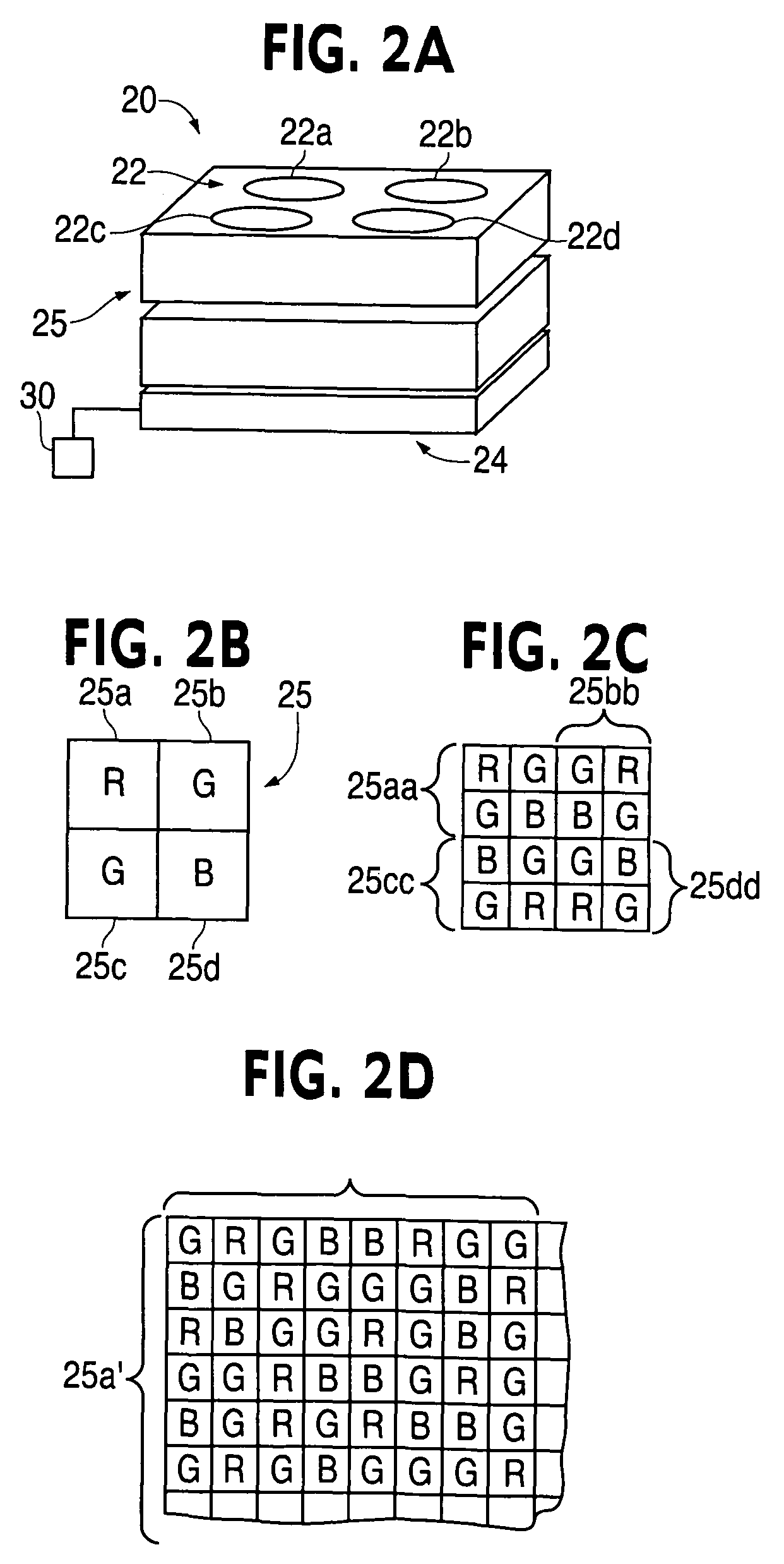
A color camera includes at least three sub-cameras, each sub-camera having an imaging lens, a color filter, and an array of detectors, The color camera combines images from the three sub-cameras to form a composite multi-color image, wherein the three sub-cameras include a total number of detectors N and a total number of different color sets X, wherein a first number of signals of a first color set is less than N / X and a second number of signals of a second color set is greater than N / X, signals of the second color set being output from at least two of the three sub-cameras, wherein resolution of a composite image of the second color set is greater than resolution of an individual sub-camera and a resolution of the composite image. Corresponding images of the same color set may be shifted, either sequentially or simultaneously, relative to one another.

Description

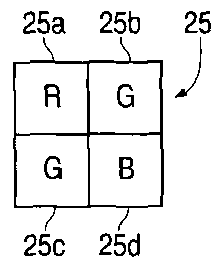
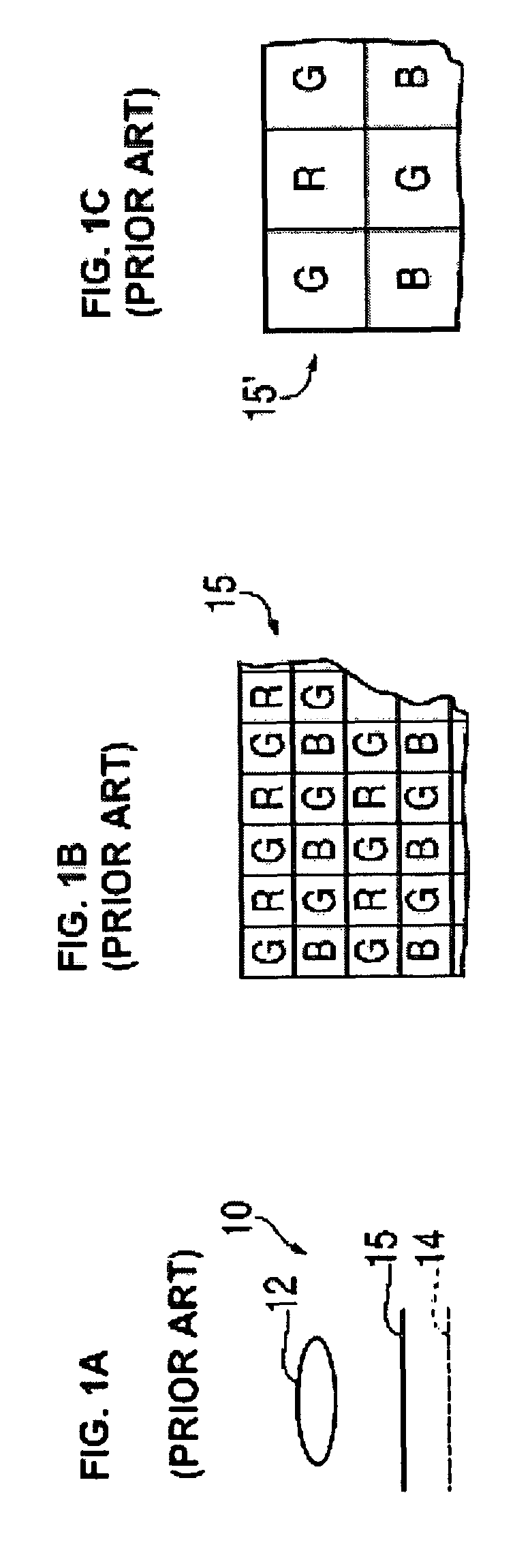
BACKGROUND OF THE INVENTION[0001]1. Field of the Invention[0002]The present invention is directed to a thin camera. More particularly, the present invention is directed to a thin camera using color filters and / or having an increased field of view.[0003]2. Description of Related Art[0004]A conventional camera 10, shown in FIG. 1A includes a lens 12 with a focal length f and a detector array 14, having a plurality of pixels. To realize color imaging, an array of filters 15 having some pattern, typically with more green filters than red or blue filters, is provided. An example of the filter array 15 is shown in FIG. 1B. Each filter in the filter array 15 corresponds to a detector, or pixel, in the detector array 14. However, this camera is relatively thick.[0005]In creating a thin color camera, one solution uses compound eye image capturing, the size of the lens being in accordance with a desired thinness of the camera. Each lens in the compound eye corresponds to a plurality of pixels...

Claims


Application Information

Patent Timeline
Patent Type & Authority Patents(United States)
IPC IPC(8): H04N5/225H04N5/335H04N9/04H04N3/14G02B7/02H04N23/12H04N25/00
CPCH04N3/1587H04N9/045G02F2201/52G02B3/0043H01L27/14621H01L27/14627G02B3/14H04N23/45H04N23/55H04N23/84H04N25/134H04N25/41H04N25/48
Inventor FELDMAN, MICHAEL R.TE KOLSTE, ROBERT
Owner DIGITALOPTICS CORPORATION
Learn More