
Head cap for aerosol type atomizer

a technology of atomizer and head cap, which is applied in the direction of liquid handling, transportation and packaging, and closure using stoppers, etc., can solve the problems of increasing the number of parts and components to form the aerosol type atomizer, affecting the operation, and affecting the operation, so as to achieve easy and safe operation, simple and uncomplicated operation, the effect of preventing the effect of explosion

Active Publication Date: 2010-08-17
FUMAKILLA LTD
View PDF16 Cites 19 Cited by
  • Summary
  • Abstract
  • Description
  • Claims
  • Application Information

AI Technical Summary

Benefits of technology

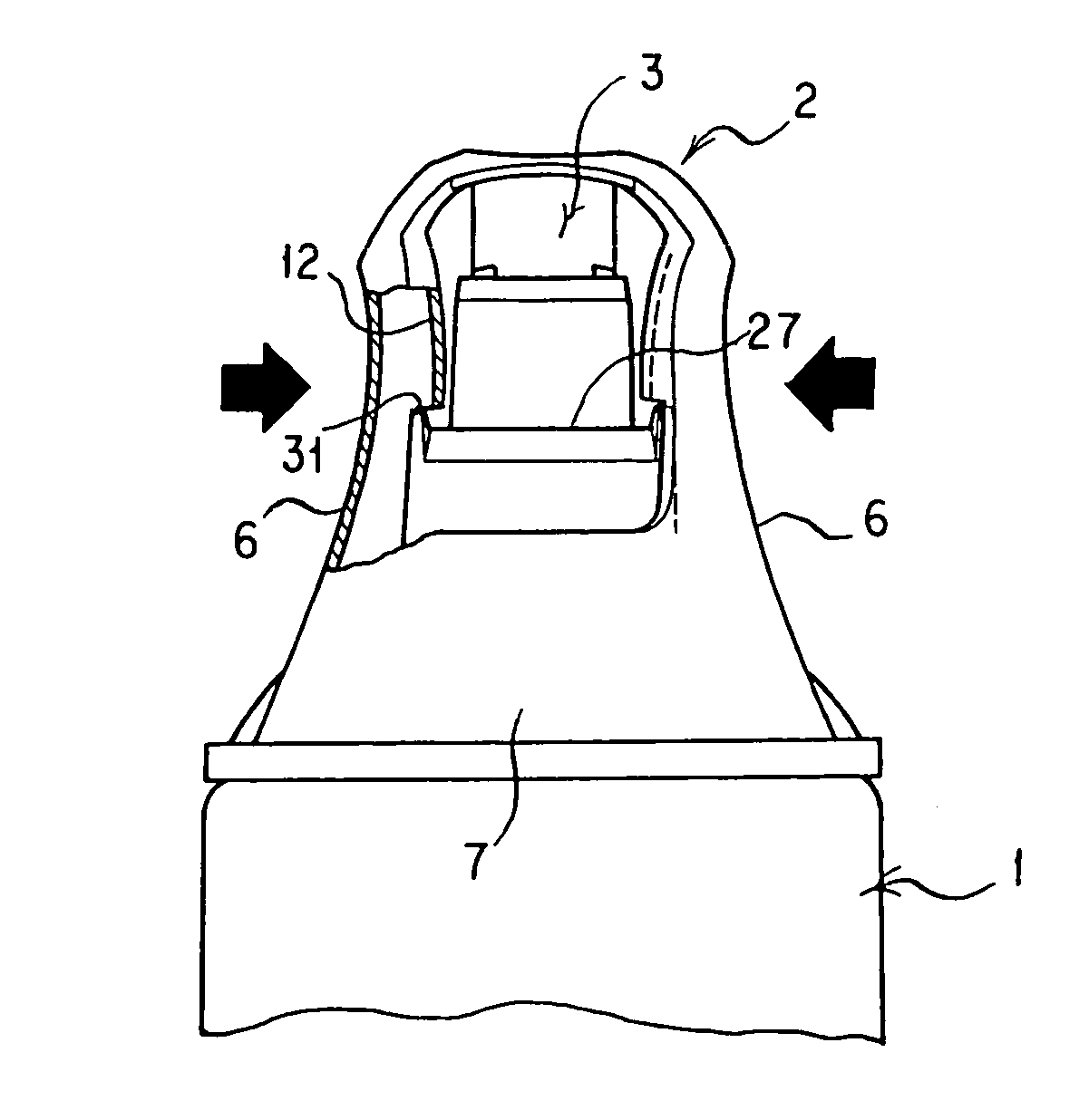
[0015]According to the present invention, in performing the operation of discharging the residual gas when the use of an aerosol type atomizer is ended, when a user pushes down the push button with fingers to take a spray position, the user may perform an extremely simple and uncomplicated operation of pressing a side face of the cap body inwards to engage the side face with the movable member for spray operation and thereby to lock the movable member for spray operation with the side face and can therefore perform the operation easily and safely.
[0016]Also, according to the present invention, since contents of the container are prevented from being sprayed unless the user performs a particular operation of holding the movable member for spray operation at the spray position by pressing the side face of the cap body inwards to lock the movable member for spray operation with the side face, the problem of falsely spraying the contents inside of the container altogether when the aerosol type atomizer is used, namely in the time of normal spray, can be prevented.

Problems solved by technology

For this reason, when the aerosol type atomizer is discarded and scrapped, there is a fear of accident that an explosion may occur due to the gas that remains in the container, namely the residual gas.
In the former type of the conventional aerosol type atomizers, the need to provide the atomizer separately with the needle or drilling tool for drilling the container gives rise to the problem of increasing the number of parts and components to form the aerosol type atomizer.
In addition, the need for its use to remove the needle or drilling tool from the aerosol type atomizer and then to pierce the container therewith has the problem of its operation being very troublesome, and yet piercing the container may cause the residual gas in the container to fly about, presenting the problem that the operation may be attended with a danger.
On the other hand, the latter can largely alleviate the problems of the operation being troublesome and becoming hazardous as in the former in that the residual gas in the container is discharged by moving the movable member for spray operation in the head cap largely downwards to fix it at the lower position (in the state of spray), but since the movable member for spray operation can be automatically fixed at the lower position (brought in the state of spray) by pushing it intensely, there is a risk that the problem arises that a false operation to push the movable member for spray operation intensely by just an inadvertence in a time of normal spray may cause the movable member for spray operation to be so fixed automatically with the result that the contents in the container are altogether sprayed.

Method used


Image

  • Head cap for aerosol type atomizer
  • Head cap for aerosol type atomizer
  • Head cap for aerosol type atomizer

Examples


Embodiment Construction

[0031]An explanation is given in respect of an embodiment of a head cap for an aerosol type atomizer according to the present invention.

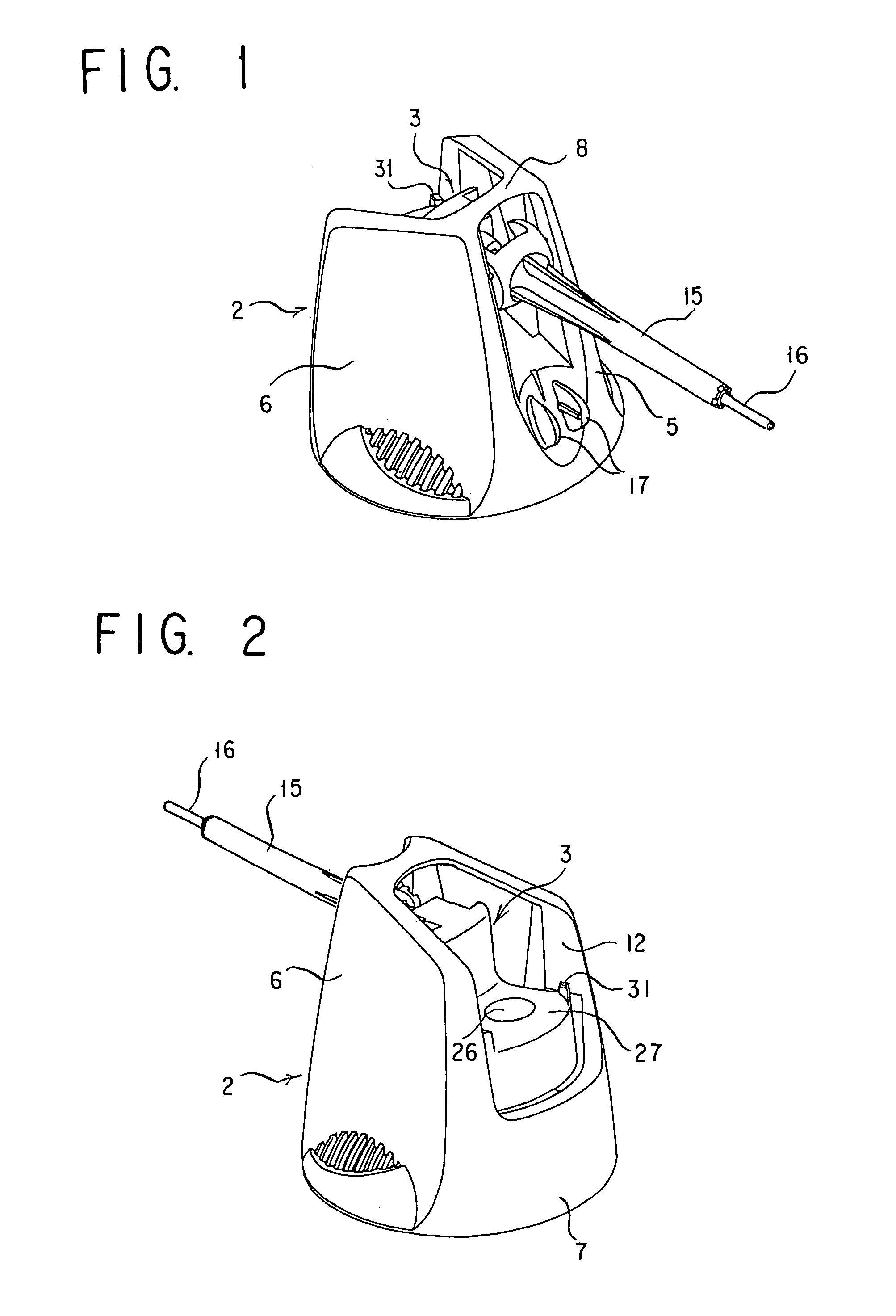
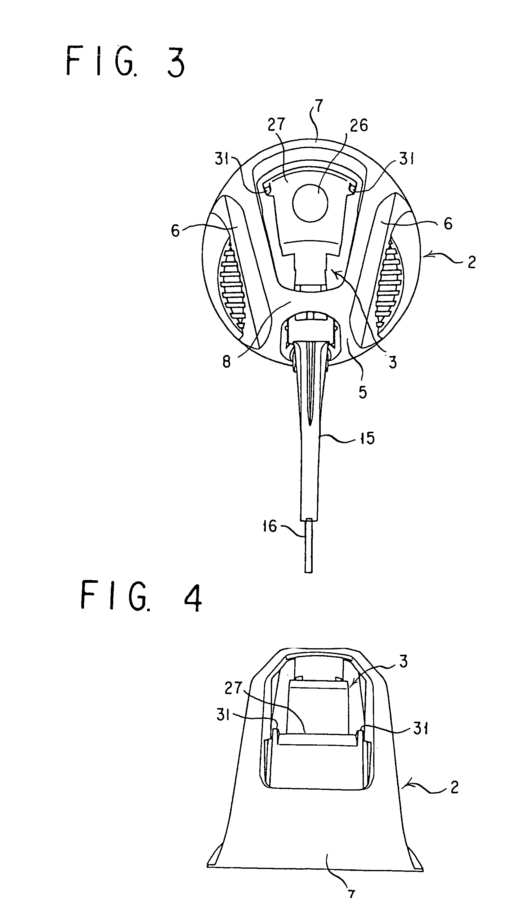
[0032]As shown in FIGS. 1 to 5, the head cap for this aerosol atomizer is basically made of a cap body 2 mounted over a top of a container 1 accommodating its contents such as a chemical in its inside, and a movable member for spray operation 3 which is disposed inside of the cap body 2, which is connected to a part of the cap body 2 and which can be pivoted and swung vertically relative to the cap body 2.

[0033]The cap body 2 comprises a front part 5 that is largely opened longitudinally, side faces 6 at its right and left hand sides that are planar for the most parts, a rear part 7 that is opened at its upper side, and a top face 8 that is opened at its rear side, the opening of the rear part 7 being continuous with that of the top face 8. Each of the side faces 6 of the right and left hand sides is made of an outer wall plate 11 and an inner wall ...


PUM


Abstract

A head cap for an aerosol type atomizer is proposed in which a residual gas that remains in the container after the use of the aerosol type atomizer is ended are discharged easily and safely, and which is so structured that the aerosol type atomizer cannot be falsely operated while it is being used. It comprises a cap body mounted over a top of a container accommodating its contents, and a movable member for spray operation disposed inside of the cap body and having a fluid channel extending from a stem fitting part for fitting with a stem and leading to a spray port, the movable member for spray operation having a push button such that pushing down the push button to take a spray position sprays contents of the container from the spray port via the fluid channel, wherein the cap body has a side face elastically deformable so that when the push button of the movable member for spray operation is pushed down to take the spray position, pressing the side face of the cap body inwards locks the movable member for spray operation with the side face to hold the movable member for spray operation at the spray position.

Description

[0001]This application is a U.S. National Phase Application under 35 USC 371 of International Application PCT / JP2006 / 301079 filed Jan. 18, 2006.TECHNICAL FIELD[0002]The present invention relates to a head cap for an aerosol type atomizer and, more particularly, to a cap head for an aerosol type atomizer in which when all the contents in a container of the aerosol type atomizer are sprayed and used up (when the use of the aerosol type atomizer is ended), a residual gas that remains in the container can be discharged.BACKGROUND ART[0003]An aerosol type atomizer is made of a container accommodating its contents such as a chemical in its inside, and a head cap mounted over a top of the container.[0004]The container which accommodates its contents such as a chemical and a gas in its inside in a sealed state is provided at its top end with a stem, which is biased upwards, can be pushed down and is structured so that when the stem is pushed down, the contents of the container may be discha...

Claims


Application Information

Patent Timeline
Patent Type & Authority Patents(United States)
IPC IPC(8): B65D83/00
CPCB65D83/205B65D83/24B65D83/303B05B9/04B65D83/14
Inventor YAMAMOTO, KAZUNORIKANEMATSU, SHINYAMASAKI, SATOSHI
Owner FUMAKILLA LTD
Learn More