Flotation drive wheel for a self-propelled irrigation system

a self-propelled irrigation and drive wheel technology, which is applied to the parts of the wheel, the wheel attachment, the wheel with the spade lug, etc., can solve the problems of uneven soil displacement on the side of the wheel track, the formation of ruts on the wheel track, and the difficulty of reducing the number of ruts, so as to reduce the formation of ruts or wheel tracks, prevent or reduce soil, and eliminate flat tire problems

Inactive Publication Date: 2010-08-17
METTENBRINK LYNN W
View PDF18 Cites 9 Cited by
  • Summary
  • Abstract
  • Description
  • Claims
  • Application Information

AI Technical Summary

Benefits of technology

[0009]The pivotal connection of the shoes to the ring-shaped band permits the shoes to pivot with respect to the wheel as the drive wheel is being rotated by the gearbox. The pivotal connection between the shoes and the ring-shaped band enables the shoes to be substantially horizontally disposed when moved into ground engagement as the drive wheel is being rotated.
[0010]The shape of the shoes and the pivotal connection thereof create sufficient flotation to the drive wheel so as to reduce the amount of wheel tracks or ruts from being created. The design of the shoes reduces the amount of soil which is normally pushed forwardly of the drive wheel as the drive wheel is rotated and also reduces the amount of soil normally displaced to either side of the drive wheel during rotation of the drive wheel.
[0012]Yet another object of the invention is to provide a flotation drive wheel for a self-propelled irrigation system which is of steel construction thereby eliminating the flat tire problems associated with conventional pneumatic drive wheels.
[0013]Still another object of the invention is to provide a flotation drive wheel for a self-propelled irrigation system which substantially reduces the formation of wheel tracks or ruts.
[0014]Still another object of the invention is to provide a flotation drive wheel for a self-propelled irrigation system which includes a plurality of floating shoes pivotally mounted to the outer periphery of the drive wheel hub portion and which prevent soil from being pushed forwardly of the rotating drive wheel and which prevents or reduces soil being pushed laterally from the drive wheel as the drive wheel is rotated.
[0015]A further object of the invention is to provide a flotation drive wheel for a self-propelled system of the type described including means for preventing dirt and mud from sticking to the shoes.

Problems solved by technology

In addition to creating wheel tracks or ruts which extend downwardly into the ground, the conventional drive wheels of the support towers cause soil to be displaced to either side of the wheel track.
When the field is being prepared for seeding or the like, the wheel tracks subject the farm machinery to undue stress.
Further, in minimum tillage or no-till fields, the wheel tracks tend to become deeper with each passing season, since the field is not cultivated or disked.

Method used


Image

  • Flotation drive wheel for a self-propelled irrigation system
  • Flotation drive wheel for a self-propelled irrigation system
  • Flotation drive wheel for a self-propelled irrigation system

Examples


Embodiment Construction

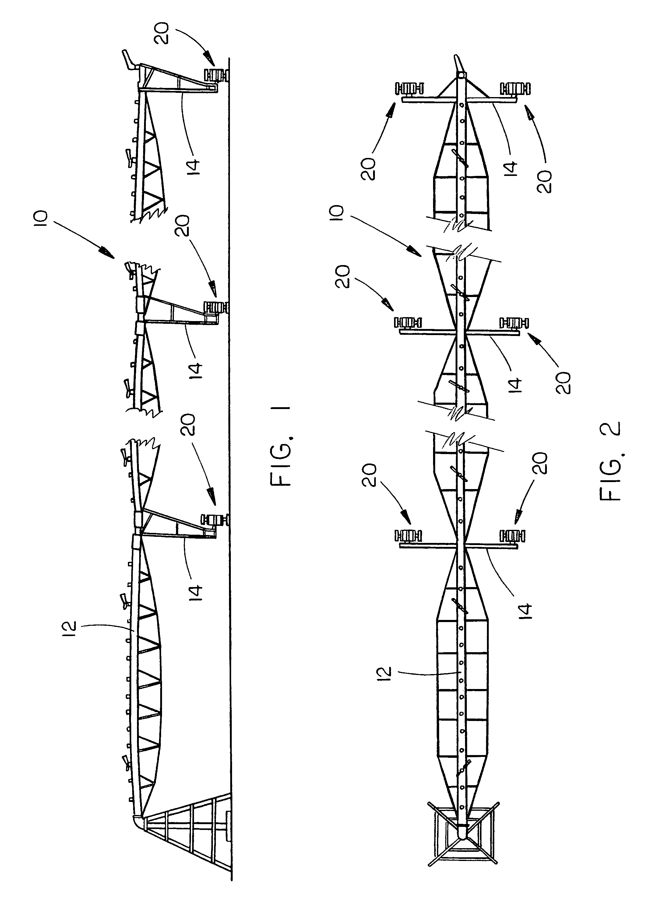
[0024]In the drawings, the numeral 10 refers to a typical center pivot irrigation system including a main water supply line 12 supported by a plurality of drive towers 14. Although a center pivot irrigation system is depicted, the irrigation system is a self-propelled irrigation system which could be a center pivot irrigation system, a linear move irrigation system or a corner irrigation system. Regardless of the type of irrigation system, the water supply pipe 12 is supported upon the drive towers 14 with each of the drive towers 14 having a pair of drive wheels mounted on the main beam 16 of the tower for propelling the tower and the water supply pipe 12 over the field to be irrigated.

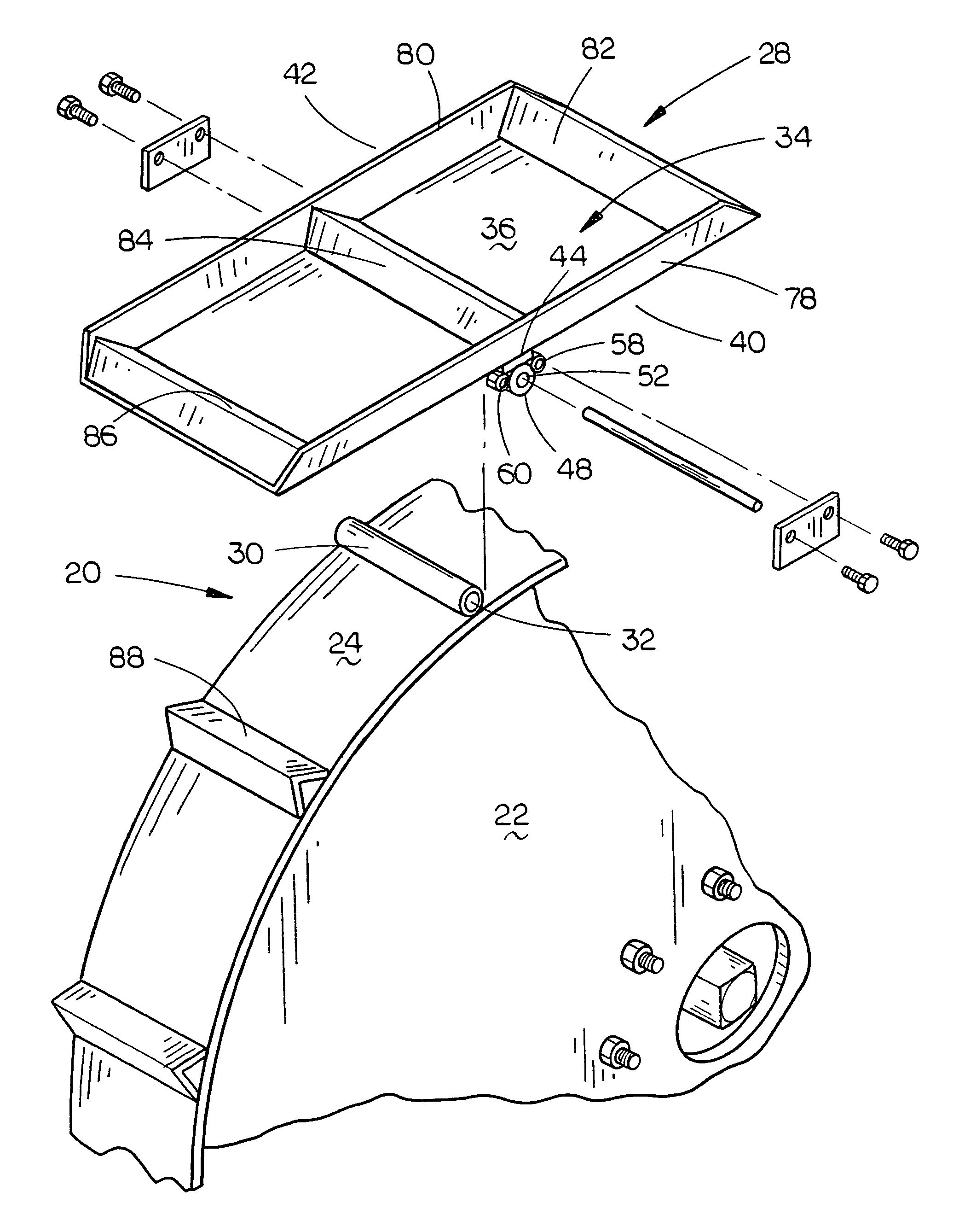
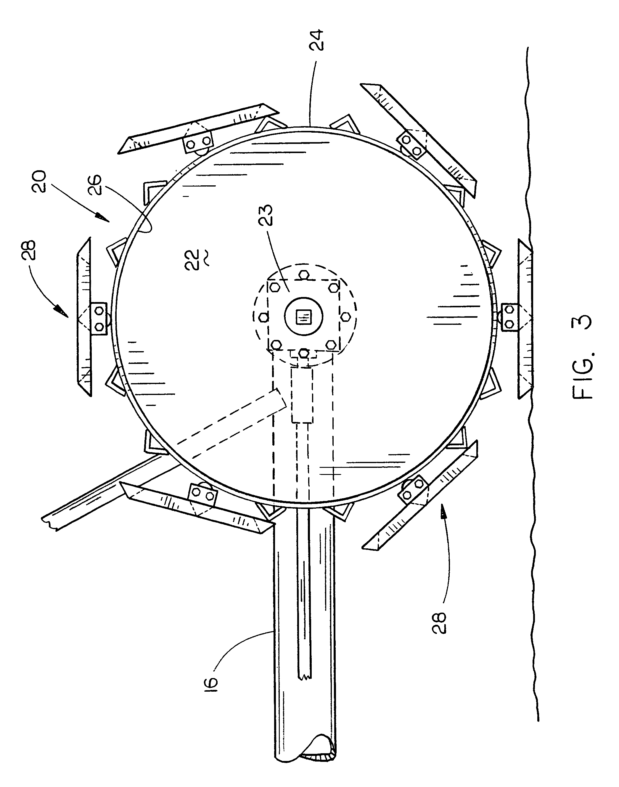
[0025]The conventional drive wheels of self-propelled irrigation systems create wheel ruts or tracks and it is for that reason that applicant has provided a unique flotation drive wheel 20 which is substituted for each of the drive wheels 16 and 18 to substantially reduce the wheel tracks or ruts whi...


PUM


Abstract

A flotation drive wheel is provided for a self-propelled irrigation system such as a center pivot irrigation system, a linear irrigation system or a corner irrigation system. The flotation drive wheel of this invention comprises a hub portion which is directly attached to an associated gearbox of the conventional drive tower. A metal band or plate is welded to the outer periphery of the hub portion of the wheel with a plurality of pivotal flotation shoes being attached to the band or plate. The pivotal shoes include structure for preventing soil from being pushed laterally of the flotation wheel and from being pushed forwardly from the drive wheel. The flotation wheel of this invention substantially eliminates the creation of wheel ruts or tracks.

Description

CROSS REFERENCE TO RELATED APPLICATION[0001]This application claims the benefit of the provisional application entitled FLOTATION DRIVE WHEEL FOR A SELF-PROPELLED IRRIGATION SYSTEM, Ser. No. 60 / 905,645, Filed Mar. 8, 2007.BACKGROUND OF THE INVENTION[0002]1. Field of the Invention[0003]This invention relates to a flotation drive wheel for a self-propelled irrigation system such as a center pivot irrigation system, a linear irrigation system or a corner irrigation system. More particularly, this invention relates to a flotation drive wheel for a self-propelled irrigation system which reduces the wheel ruts or tracks normally created by the drive wheels of the irrigation system.[0004]2. Description of the Related Art[0005]Self-propelled irrigation systems such as a center pivot irrigation system, a linear irrigation system or a corner irrigation system utilize drive towers which not only support the main water supply pipe above the ground, but which also drive the irrigation system ove...

Claims


Application Information

Patent Timeline
Patent Type & Authority Patents(United States)
IPC IPC(8): B60B15/18
CPCB60B15/06
Inventor METTENBRINK, LYNN W.
Owner METTENBRINK LYNN W
Why Eureka
Try Eureka