Focal plane shutter for cameras

a technology for camera shutters and planes, applied in shutters, optics, instruments, etc., can solve the problems of increasing the size of the electromagnet or consumption of batteries, unable to obtain sufficient sucking force and holding force of the electromagnet, and unable to stop the rotation of the driving member, etc., to achieve smooth tilting and stable exposure operation of the shutter blade.

Active Publication Date: 2010-08-17
COPAL CO LTD
View PDF18 Cites 0 Cited by
  • Summary
  • Abstract
  • Description
  • Claims
  • Application Information

AI Technical Summary

Benefits of technology

[0014]The present invention is achieved to solve these problems, and has an object to provide a focal plane shutter for cameras in which when a member for mounting an iron scrap member having an iron scrap portion at one end of a shaft and a flange at the other end via a compression spring brings the iron scrap portion into tight contact with an iron core member of an electromagnet against elasticity of the compression spring, the shaft of the iron scrap member can be suitably tilted, and when the member for mounting the iron scrap member is slightly operated until being stopped by the flange after the iron scrap portion is sucked by the iron core member from a state where the flange is placed away from a mounting portion of the iron scrap member, any tilt of the shaft of the iron scrap member does not cause the iron scrap member to abut part of an outer peripheral portion of the flange to be damaged or to be affected by an operation of a shutter blade.
[0017]Alternatively, the driving means includes a driving member connected to the shutter blade and rotated by elasticity of the driving spring in photography, a locking member that locks the driving member in a set position, the mounting member that releases the lock of the driving member by the locking member when the coil is deenergized in photography, and a holding member that presses the mounting member to bring the iron scrap member into contact with the iron core member in setting and releases the press after the coil is energized, thereby obtaining a good locking type focal plane shutter for cameras.
[0018]Alternatively, the driving means includes a driving member connected to the shutter blade and rotated by elasticity of the driving spring in photography, a locking member that locks the driving member in a set position, the mounting member that is operated together with the driving member to the set position by the setting member in setting, and releases the lock of the driving member by the locking member when the coil is deenergized after the setting member returns to the initial position in photography, thereby obtaining another good locking type focal plane shutter for cameras.
[0020]The present invention provides the focal plane shutter for cameras in which an iron scrap member having the iron scrap portion at one end of the shaft and the flange at the other end, the sucked surface of the iron scrap portion is brought into tight contact with the sucking surface of the iron core member of the electromagnet by elasticity of the spring in setting, sucked and held by the iron core member when the coil of the electromagnet is energized in an initial stage of a release of a camera, then separated from the iron core member when the coil is deenergized, thereby allowing the shutter blade to be moved by the driving member, wherein the edge of the mounting hole of the iron scrap member is formed to have the arcuate surface as is conventional, and the collar member having a special shape is fitted to the shaft of the iron scrap member in contact with the arcuate surface and the flange. Thus, when the iron scrap portion of the iron scrap member is brought into tight contact with the iron core member, the shaft of the iron scrap member can be smoothly tilted. Also, when the iron scrap portion is brought into tight contact with the iron core member, any tilt of the shaft does not cause only part of the outer peripheral portion of the flange to abut the mounting portion of the iron scrap member, thereby always allowing a stable exposure operation of the shutter blade.

Problems solved by technology

Thus, if a sucked surface of the iron scrap member is tilted with respect to a sucking surface of the electromagnet at the start of energization, and both the surfaces are not in tight contact with each other, a sufficient sucking and holding force by the electromagnet cannot be obtained, and the driving member starts rotation by the biasing force of the driving spring before predetermined timing to cause the shutter blade to start an exposure operation.
Specifically, in terms of production, it is difficult to stop rotation of the driving member at the moment when the iron core member and the iron scrap portion are brought into tight with each other in setting.
In order to prevent this, a suction force by the electromagnet may be increased, which increases the size of the electromagnet or consumption of a battery.
Further, the edge of the mounting hole repeatedly abuts part of the peripheral portion of the tilted flange, the edge of the mounting hole is damaged, thereby preventing the tight contact state as described above from being obtained.
On the other hand, with the configuration such that the edge of the mounting hole abuts only part of the peripheral portion of the flange, when the coil of the electromagnet is deenergized, and the driving member starts rotation at predetermined timing, the edge of the mounting hole is brought into contact with the entire surface of the flange, and rattles at that time may affect a stable movement of the shutter blade.
However, when the iron scrap member is tilted on a surface perpendicular to the rotation surface of the driving member, there is little problem if a thickness of the mounting portion (a vertical dimension with respect to the rotation surface) is smaller than a diameter of the flange, but the iron scrap member cannot be suitably tilted if the thickness of the mounting portion is equal to or larger than the diameter of the flange, thereby preventing desired advantages from being sufficiently provided.
Also in the mounting configuration of the iron scrap member described in Japanese Utility Model Laid-Open No. 56-53310, the configuration is suitable when the iron scrap member is tilted on one plane, but does not allow the iron scrap member to be suitably tilted in a direction perpendicular to the plane.

Method used


Image

  • Focal plane shutter for cameras
  • Focal plane shutter for cameras
  • Focal plane shutter for cameras

Examples


embodiment 1

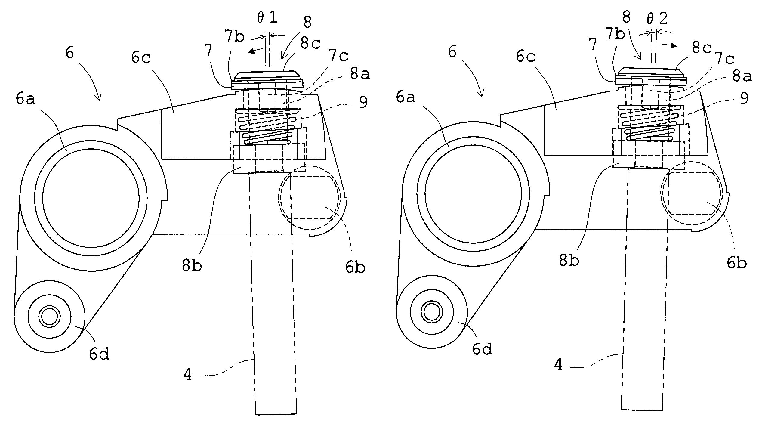
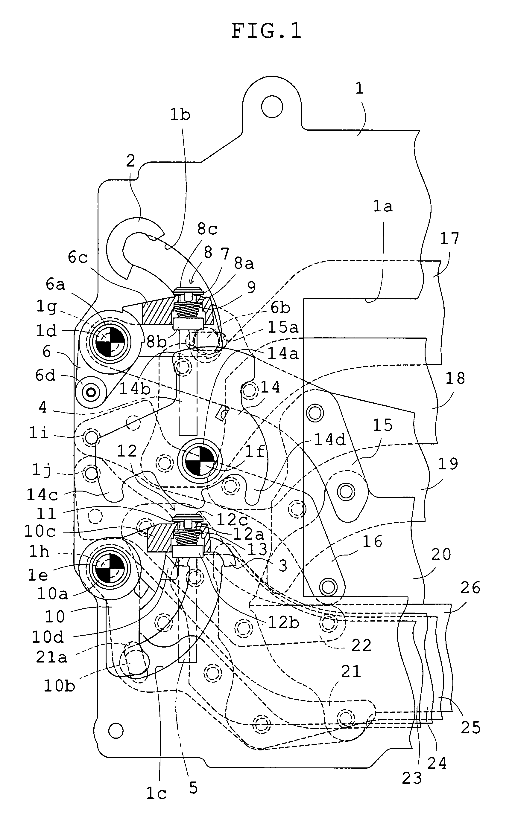
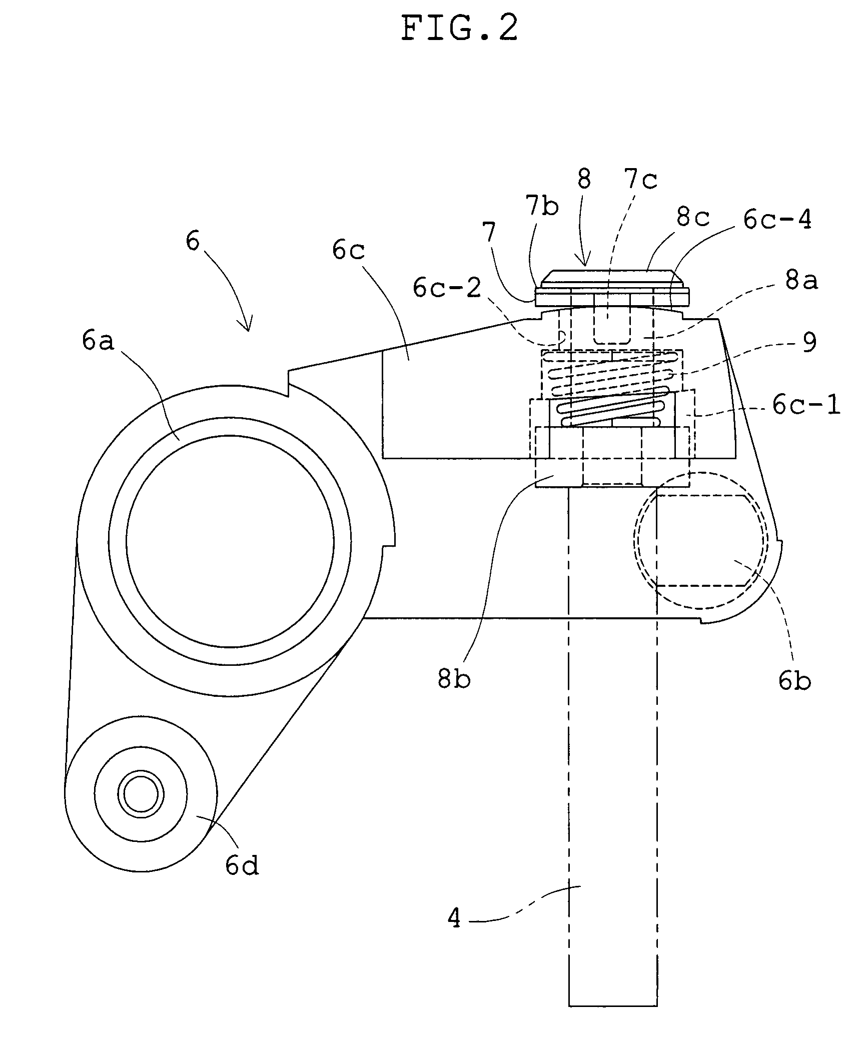
[0050]Embodiment 1 will be described with reference to FIGS. 1 to 9. FIG. 1 is a plan view showing a state immediately before an exposure operation is started. FIG. 2 is an enlarged plan view of a front blade driving member in the state in FIG. 1, and FIG. 3 is a side view, partially omitted, of the front blade driving member viewed from the right in FIG. 2. FIG. 4 shows a collar member mounted to the front blade driving member, FIG. 4A is a plan view and FIG. 4B is a sectional view taken along the line A-A in FIG. 4A. FIG. 5 is a perspective views of a mounting state of the collar member and the iron scrap member 8 to the front blade driving member, FIG. 5A is a view from a flange side of an iron scrap member, and FIG. 5B is a view from an iron scrap portion side of the iron scrap member. FIG. 6 is a plan view showing a state immediately after the exposure operation is finished, and FIG. 7 is a plan view showing a set state. FIGS. 8 and 9 show a state where a shaft of the iron scra...

embodiment 2

[0079]Next, Embodiment 2 of the present invention will be described with reference to FIGS. 13 to 26. FIG. 13 is a plan view showing an opening and closing driving mechanism in a set state, FIG. 14 is a plan view showing a lock releasing mechanism in the set state, and FIG. 15 is a side view, partially enlarged, of the lock releasing mechanism in FIG. 14. FIG. 16 shows a state where a holding force of a holding member for holding two releasing members is released from the state in FIG. 14, FIG. 17 shows a state where a lock of the front blade driving member is released from the state in FIG. 16, and FIG. 18 shows a state where an opening operation of a front blade is completed. FIG. 19 shows a state where a lock of a rear blade driving member is released from the state in FIG. 17, and FIG. 20 shows a state where a closing operation of a rear blade is completed. FIG. 21 shows a state immediately after a setting operation is started after the state in FIG. 20, and FIG. 22 shows a stat...


PUM


Abstract

A focal plane shutter for cameras includes: a shutter blade assembly; an electromagnet assembly; driving means that includes a mounting member mounted with an iron scrap member that cooperates with an iron core member of the electromagnet assembly; and a setting member that operates the driving means to a set position. The iron scrap member includes a shaft fitted in a mounting hole of the mounting member, an iron scrap portion provided at one end of the shaft and brought into contact with the iron core member, and a removal preventing flange provided at the other end of the shaft, a collar member is fitted to the shaft between the mounting hole and the flange, an edge of the mounting hole is formed to have an arcuate surface protruding toward the collar member, and the collar member is formed to have, on the edge side, an arcuate surface protruding toward the flange and substantially perpendicular to the arcuate surface.

Description

BACKGROUND OF THE INVENTION[0001]1. Field of the Invention[0002]The present invention relates to a focal plane shutter for cameras having one or two shutter blades.[0003]2. Description of the Related Art[0004]Two types of focal plane shutters for cameras are known. One includes two shutter blades (a front blade and a rear blade) and the other includes one shutter blade. The former including two shutter blades has been adopted in silver film cameras and digital cameras, while the latter inducing one shutter blade has been adopted only in digital cameras. In the focal plane shutter of either type, each shutter blade is constituted by two arms individually pivoted at one end on a surface of a shutter base plate on a blade chamber side, and at least one blade pivoted on both of the arms.[0005]A driving member for a shutter blade is rotatably mounted to a surface of the shutter base plate outside the blade chamber, and a driving pin thereof is connected to one arm of the shutter blade in...

Claims


Application Information

Patent Timeline
Patent Type & Authority Patents(United States)
IPC IPC(8): G03B9/08
CPCG03B9/08
Inventor ICHIHARA, MASAKATSUINOUE, NOBUYOSHI
Owner COPAL CO LTD
Why Eureka
Try Eureka