Electrical connector having improved grounding member

a technology of grounding member and electric connector, which is applied in the direction of two-part coupling device, coupling device connection, printed circuit, etc., can solve the problem that electric magnetic interference cannot be effectively reduced, and achieve the effect of effective reduction of electrical magnetic interferen

Active Publication Date: 2010-08-17
HON HAI PRECISION IND CO LTD
View PDF5 Cites 15 Cited by
  • Summary
  • Abstract
  • Description
  • Claims
  • Application Information

AI Technical Summary

Benefits of technology

[0006]One object of the present invention is to provide an electrical connector having a grounding member forming a plurality of grounding circuits for effectively reducing electrical magnetic interference.
[0008]Advantages of the present invention are to provide a first grounding circuit established between the outer shield and the mother printed circuit board via the grounding member, and a second grounding circuit established between the outer shield and the mother printed circuit board via the tines formed on the outer shield. It is effective to reduce the electrical magnetic interference via the first and the second grounding circuits.

Problems solved by technology

The electrical magnetic interference could not be effectively reduced by only one grounding trace established between the pins of the outer shield and the printed circuit board.

Method used


Image

  • Electrical connector having improved grounding member
  • Electrical connector having improved grounding member
  • Electrical connector having improved grounding member

Examples


Embodiment Construction

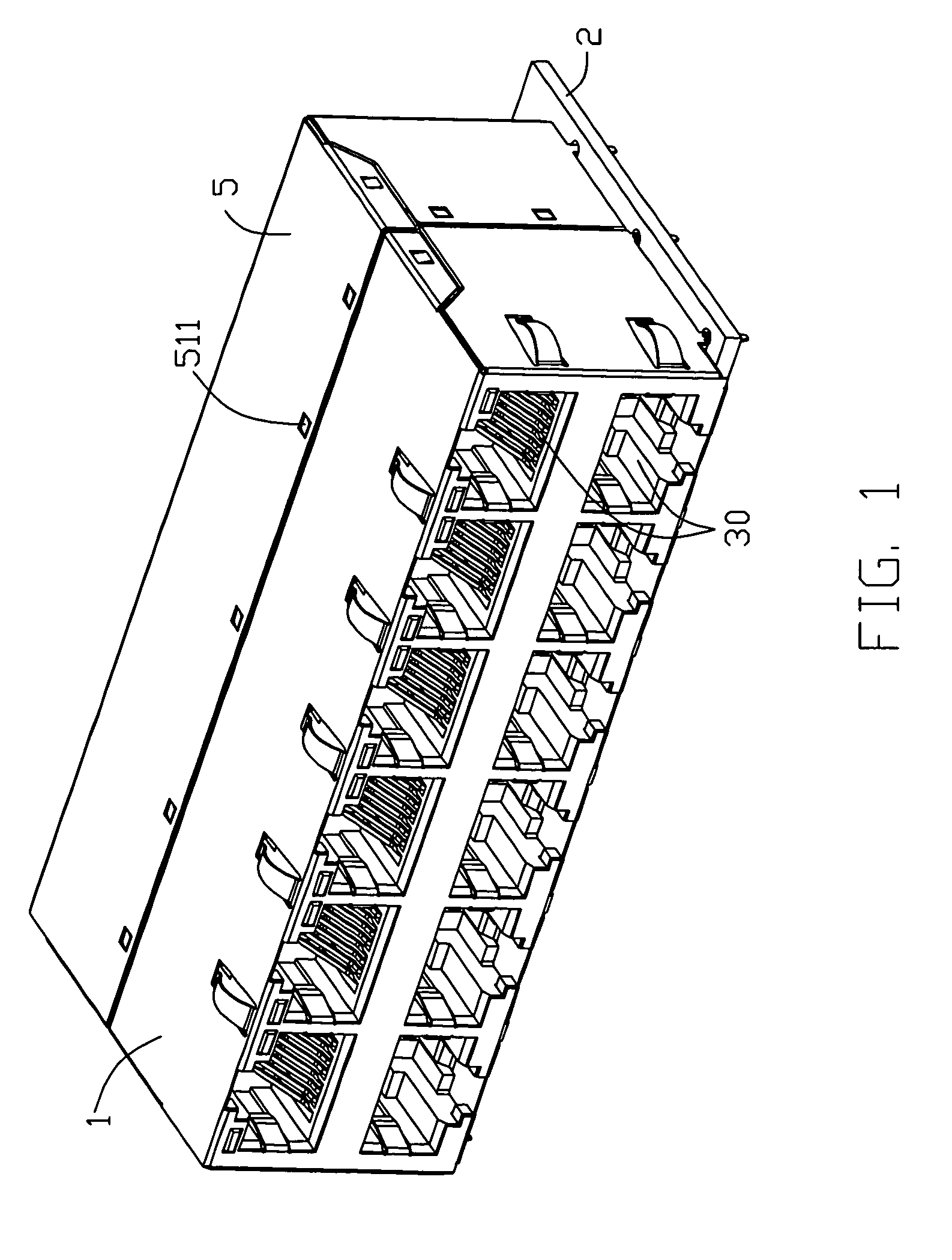
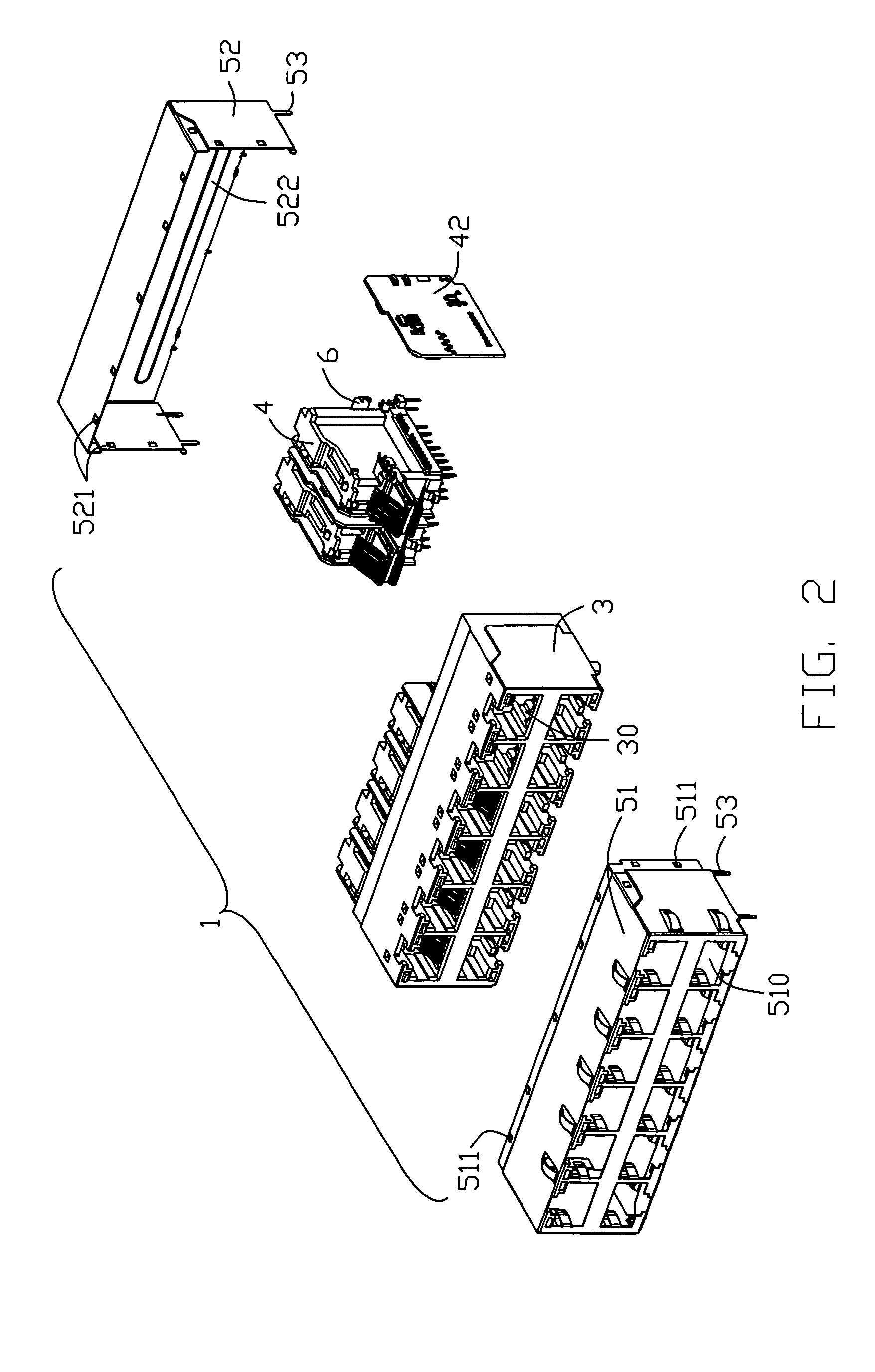
[0014]Reference will now be made to the drawing figures to describe the pre-sent invention in detail. Referring to FIGS. 1-2, an electrical connector 1 mounted onto a mother printed circuit board 2 in accordance with the present invention comprises an insulative housing 3, a plurality of contacting modules 4 mounted into the insulative housing 3, a grounding member 6 assembled to the contacting module 4 and an outer shield 5 enclosing the insulative housing 3.

[0015]As shown in FIG. 2, the insulative housing 3 has two arrays of openings 30 profiled one above the other for receiving mating plugs (not shown).

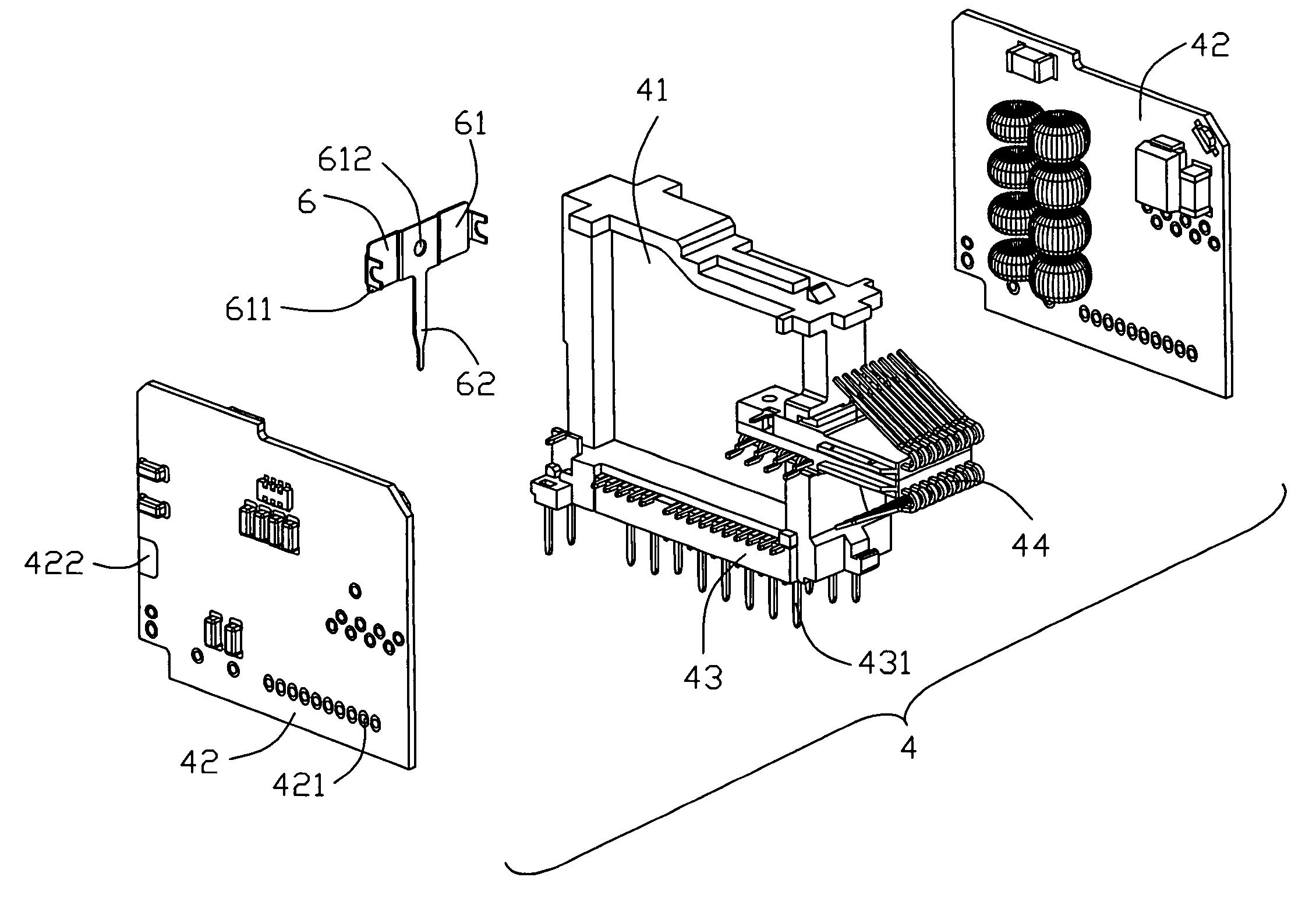
[0016]As shown in FIGS. 3 and 4, the contacting module 4 includes a medial element 41, a terminal element 44 mounted to a front portion of the medial element 41 for engaging with corresponding mating plug, a pair of daughter printed circuit boards 42 mounted to opposite sides of the medial portion 41 and a connecting element 43 assembled to a bottom portion of the medial element 41...


PUM


Abstract

An electrical connector (1) mounted on a mother printed circuit board (2) includes an insulative housing (3), a contacting module (4) having a pair of daughter printed circuit boards (42), a grounding member (6) and an outer shield (5) enclosing the insulative housing. The grounding member has a base portion (61) connecting to the daughter printed circuit board and a contacting portion (62) extending downwardly for connecting with the mother printed circuit board. The outer shield has a protruding member (522) for contacting with the grounding member and a number of tines (53) extending downwardly therefrom in contact with the mother printed circuit board for grounding.

Description

BACKGROUND OF THE INVENTION[0001]1. Field of the Invention[0002]The present invention relates to an electrical connector, and particularly to an electrical connector having a grounding member forming a plurality of grounding circuits for eliminating interference caused by static electricity thereby ensuring reliable signal transmission between the connector and a mating connector.[0003]2. Description of the Prior Art[0004]A conventional modular connector mounted onto a printed circuit board comprises an insulative housing and an outer shield enclosing the insulative housing. The outer shield has a plurality of openings therethrough for engaging with corresponding plug connector and a plurality of pins extending downwardly for grounding contact with the printed circuit board. The electrical magnetic interference could not be effectively reduced by only one grounding trace established between the pins of the outer shield and the printed circuit board.[0005]Hence, an improved electrica...

Claims


Application Information

Patent Timeline
Patent Type & Authority Patents(United States)
IPC IPC(8): H01R13/60
CPCH01R23/6873H01R12/724H01R13/6594H01R12/00
Inventor ZHANG, HONG-BO
Owner HON HAI PRECISION IND CO LTD
Why Eureka
Try Eureka