Spread spectrum clock signal generator

a clock signal and spectrum clock technology, applied in the field of spread spectrum clock signal generators, can solve the problems of high circuit cost and high circuit complexity of plls

Inactive Publication Date: 2009-12-31
RAYDIUM SEMICON
View PDF2 Cites 9 Cited by
  • Summary
  • Abstract
  • Description
  • Claims
  • Application Information

AI Technical Summary

Benefits of technology

[0009]Example of the invention is directed to a spread spectrum clock signal generator for spreading an input clock signal into a clock signal, which can be used as a clock signal source of an electronic system so that a problem of electronic magnetic interference (EMI) of the electronic system can be reduced.

Problems solved by technology

However, the PLL has the drawbacks of the high circuit complexity and the high circuit cost.

Method used


Image

  • Spread spectrum clock signal generator
  • Spread spectrum clock signal generator
  • Spread spectrum clock signal generator

Examples


first embodiment

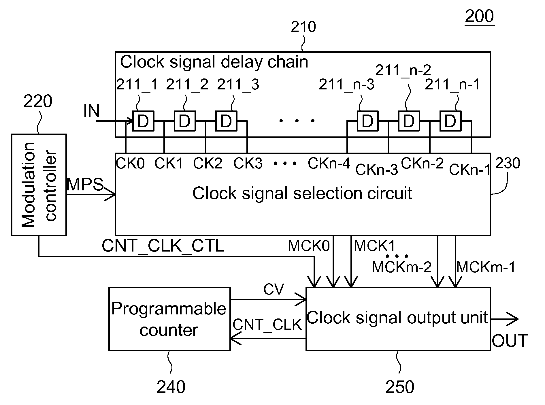
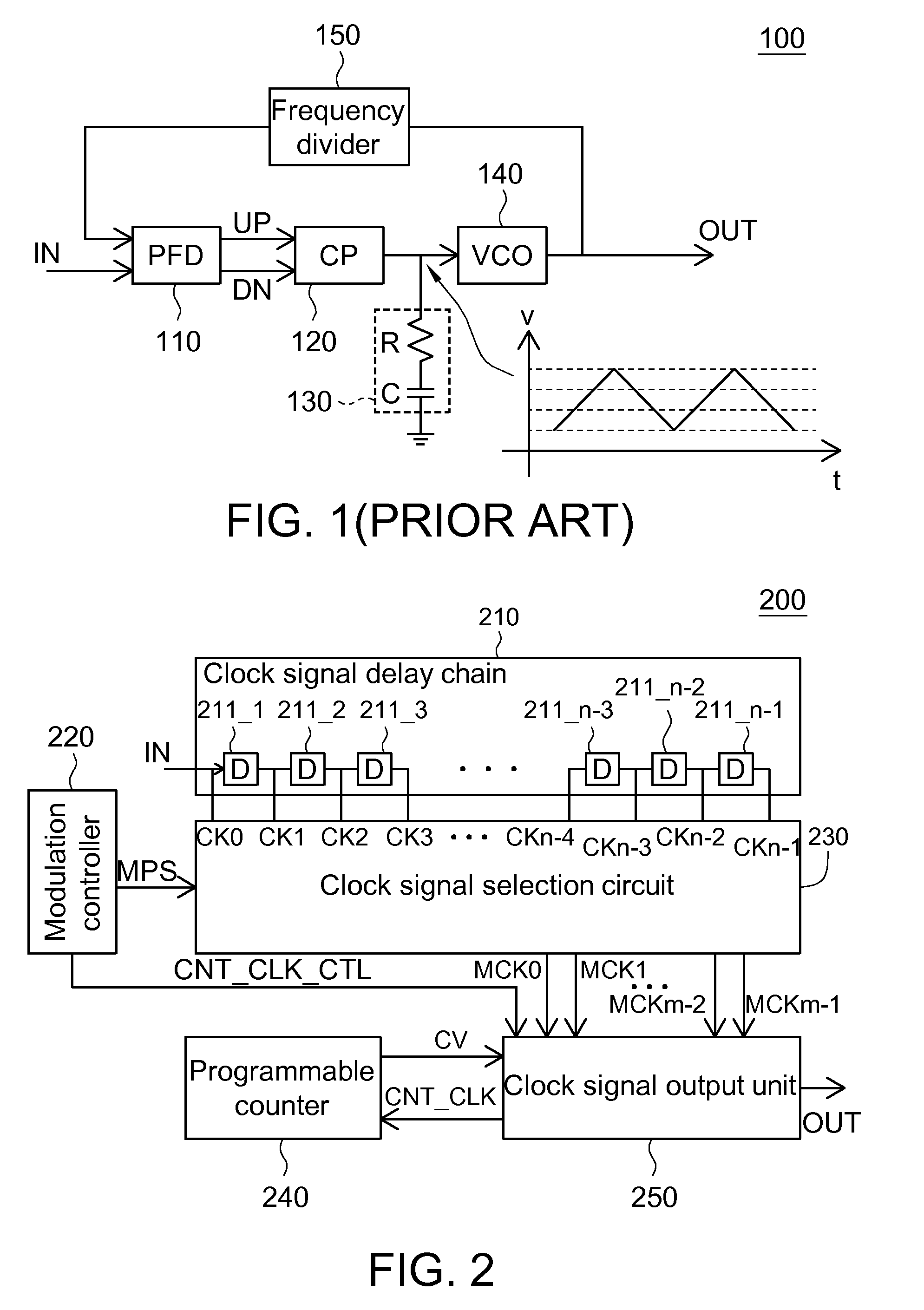
[0026]FIG. 2 is a circuit block diagram showing a spread spectrum clock signal generator 200 according to a first embodiment of the invention. Referring to FIG. 2, the spread spectrum clock signal generator 200 includes a clock signal delay chain 210, a modulation controller 220, a clock signal selection circuit 230, a programmable counter 240 and a clock signal output unit 250. The spread spectrum clock signal generator 200 spreads an input clock signal IN into an output clock signal OUT.

[0027]The clock signal delay chain 210 delays the input clock signal IN into a plurality of delay clock signals CK0 to CKn-1. The clock signal delay chain 210 includes a plurality of cascaded delaying units (D)211_1 to 211—n-1, wherein n is a positive integer. Each delaying unit outputs a respective delay clock signal. For example, the delaying unit 211_3 delays the delay clock signal CK2 into the delay clock signal CK3. The delay clock signal CK0 is the input clock signal IN. The delaying unit is,...

second embodiment

[0048]FIG. 9 is a circuit block diagram showing a spread spectrum clock signal generator 900 according to a second embodiment of the invention. Referring to FIG. 9, the spread spectrum clock signal generator 900 includes a clock signal delay chain 910, a modulation controller 920, a clock signal selection circuit 930, a programmable counter 940 and a clock signal output unit 950. The elements 910, 940 and 950 are similar to or the same as the elements 210, 240 and 250 of FIG. 2, so detailed thereof will be omitted. The clock signal delay chain 910 includes a plurality of cascaded delaying units 911_1 to 911—n-1.

[0049]The clock signal selection circuit 930 receives the counting value CV and, based on the counting value CV, selects some signals from the delay clock signals CK0 to CKn-1 to serve as the modulation clock signals MCK0 to MCKm-1. It is assumed that n=20 and m=8. For example, when the counting values CV are respectively 0, 1, 2, 3, 4, 5, 6 and 7, the signals CK0, CK3, CK5, ...


PUM


Abstract

A spread spectrum clock signal generator for spreading an input clock signal into an output clock signal includes a clock signal delay chain for delaying the input clock signal into a delay clock signal group having a plurality of delay clock signals, a modulation controller for outputting a counter clock signal control signal, a clock signal selection circuit for selecting, from the delay clock signal group, a modulation clock signal group having a plurality of modulation clock signals, a programmable counter for generating a counting value according to a counter clock signal, and a clock signal output unit for combining the modulation clock signals into the output clock signal according to the counting value, and further generating the counter clock signal, outputted to the programmable counter, according to the counter clock signal control signal.

Description

[0001]This application claims the benefit of Taiwan application Serial No. 97124104, filed Jun. 27, 2008, the subject matter of which is incorporated herein by reference.BACKGROUND OF THE INVENTION[0002]1. Field of the Invention[0003]The invention relates in general to a spread spectrum clock signal generator (SSCG) for spreading a clock signal to reduce the electronic magnetic interference (EMI) of an electronic system.[0004]2. Description of the Related Art[0005]In an electronic system, when the EMI problem is encountered, the clock signal may be spread to reduce the EMI. When the frequency of the input clock signal is changed with time, the clock signal may be spread.[0006]At present, most spectrum spreading techniques are achieved using a phase locked loop (PLL). FIG. 1 (Prior Art) is a block diagram showing a conventional phase locked loop (PLL) 100. Referring to FIG. 1, the PLL 100 includes a phase frequency detector (PFD) 110, a charge pump (CP) 120, a filter 130, a voltage c...

Claims


Application Information

Patent Timeline
Patent Type & Authority Applications(United States)
IPC IPC(8): H04B1/00
CPCH04B15/04
Inventor CHAN, CHIEN-YUHUNG, SHAO-PINGSHIH, JUN-REN
Owner RAYDIUM SEMICON
Why Eureka
Try Eureka