

Electrically conductive shield for refrigerator
A conductive shielding and refrigerator technology, which is applied in refrigerators, refrigeration and liquefaction, circuits, etc., can solve the problems of expensive bismuth alloys and lack of thermal conductivity.
- Summary
- Abstract
- Description
- Claims
- Application Information
AI Technical Summary
Problems solved by technology
Method used
Image

Examples
Embodiment Construction
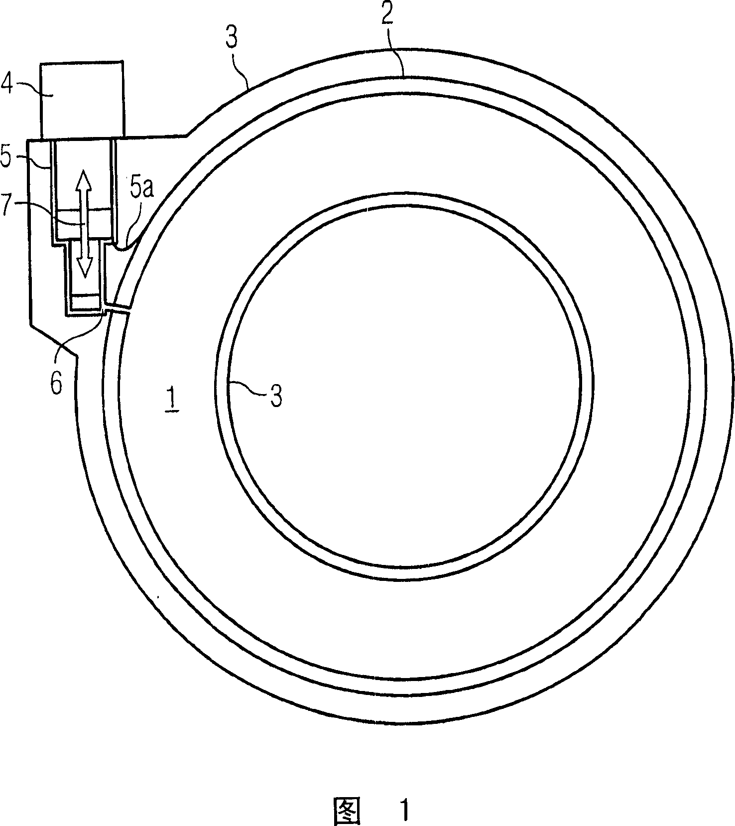
[0014] FIG. 1 shows a schematic diagram of a cryogenic magnet system equipped with a refrigerator 4 in a connection sleeve 5 . The particular cryogenic magnet system shown is an MRI magnet system. A liquid cryogen container 1 containing a superconducting magnet (not shown) is surrounded by one or more heat shields 2 which in turn are completely surrounded by a vacuum jacket 3 . Refrigerator 4 is detachably assembled to the magnet system, and is thermally and mechanically connected by connection sleeve 5, so as to cool the heat shield 2 through thermal connection 5a, which may be copper braided wire or Any other suitable known thermal connection. Although not required by the present invention, the interior of the connecting sleeve 5 may communicate with the interior of the cryogen container 1 , for example via a tube 6 . The refrigerator 4 can then recondense the evaporated refrigerant gas and convey it back to the refrigerant container 1 via the line 6 . During operation of...
PUM
 Abstract
Description
Claims
Application Information