Optical apparatus with image stabilizing and movable lenses and actuators for shifting and/or moving the lenses

a technology of image stabilization and optical equipment, applied in the field of optical equipment, to achieve the effect of suppressing magnetic influence and reducing magnetic interferen

Inactive Publication Date: 2012-04-17
CANON KK
View PDF8 Cites 7 Cited by
  • Summary
  • Abstract
  • Description
  • Claims
  • Application Information

AI Technical Summary

Benefits of technology

[0007]The present invention provides an optical apparatus capable of reducing magnetic interference between an actuator for moving a movable lens and an actuator for shifting an image stabilizing lens and capable of suppressing magnetic influence due to the actuators on magnetic sensors detecting positions of the lenses.

Problems solved by technology

Therefore, the lens moving actuator and the one of the two image stabilizing actuators magnetically interfere with each other, which influences operations of these actuators.

Method used


Image

  • Optical apparatus with image stabilizing and movable lenses and actuators for shifting and/or moving the lenses
  • Optical apparatus with image stabilizing and movable lenses and actuators for shifting and/or moving the lenses
  • Optical apparatus with image stabilizing and movable lenses and actuators for shifting and/or moving the lenses

Examples


embodiment 1

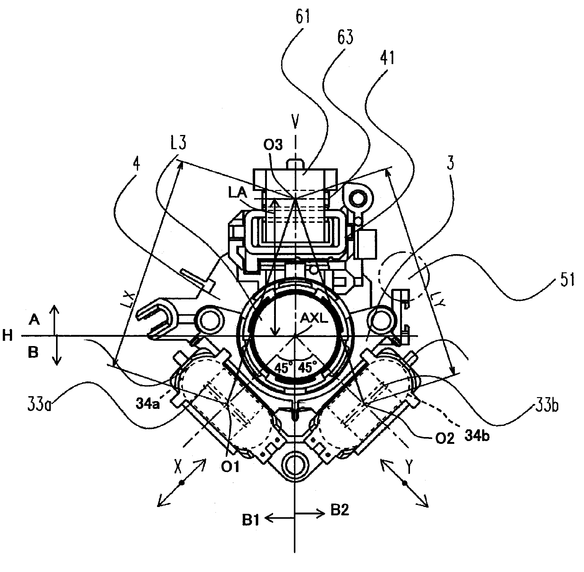
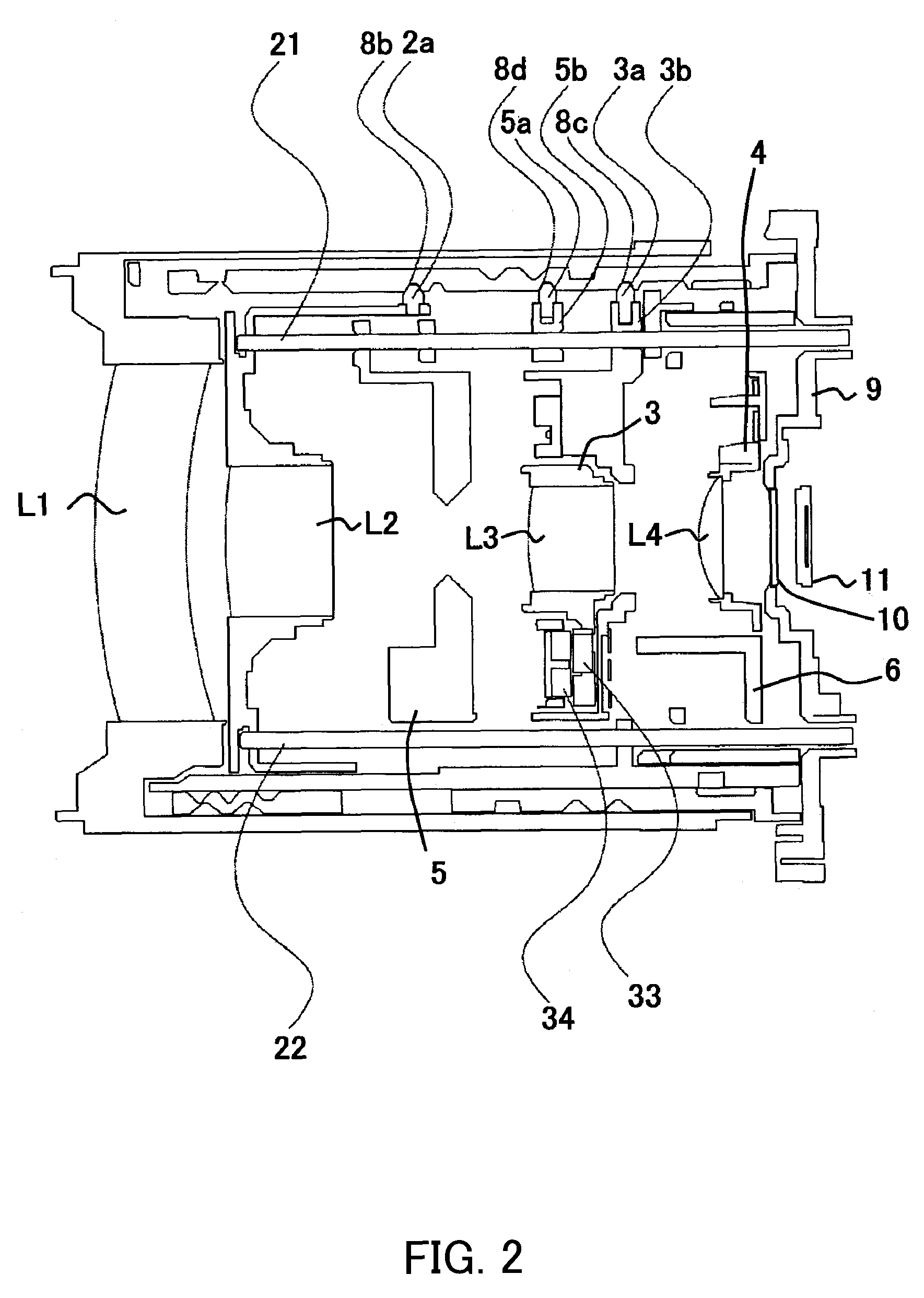
[0027]FIGS. 1 to 6 show the configuration of a lens barrel part of an image pickup apparatus (a digital still camera or a video camera) as an optical apparatus that is a first embodiment (Embodiment 1) of the present invention. FIG. 1 is a side cross sectional view of the lens barrel part at its retracted position. FIG. 2 is a top cross sectional view of the lens barrel part at the retracted position. FIG. 3 is a side cross sectional view of the lens barrel part at its WIDE (wide-angle end) position, and FIG. 4 is a top cross sectional view of the lens barrel part at the WIDE position. FIG. 5 is a side cross sectional view of the lens barrel part at its TELE (telephoto end) position. FIG. 6 is a top cross sectional view of the lens barrel part at the TELE position.

[0028]The lens barrel unit includes thereinside an optical system comprises a first lens unit L1, a second lens unit L2, a third lens unit (correcting lens that is an image stabilizing lens) L3 and a fourth lens unit (focu...

embodiment 2

[0084]Embodiment 1 has described the operation in which the parameters used by the CPU 100 for controlling the first and second image stabilizing actuators are changed according to the distance in the optical axis direction between the image stabilizing actuators and the focusing actuator. In a second embodiment (Embodiment 2) of the present invention, instead of or in addition to that operation, parameters used by the CPU 100 for controlling the focusing actuator according to the zoom position (that is, the distance in the optical axis direction between the image stabilizing actuators and the focus actuator) are changed. The parameters include, for example, an integration gain in a feedback loop using the signal from the MR sensor 67. However, parameters other than this parameter may be changed. The basic configuration of an image pickup apparatus of this embodiment is the same as that of Embodiment 1. In the present embodiment, components having same or similar functions as those ...


PUM


Abstract

The optical apparatus includes an image stabilizing lens shiftable with respect to an optical axis, a movable lens movable in an optical axis direction, first and second actuators shifting the image stabilizing lens, and a third actuator moving the movable lens. The first, second and third actuators include a magnet and a coil. When viewed in the optical axis direction, the first and second actuators are disposed in a first area and the third actuator is disposed in a second area, the first and second areas being opposite to each other with respect to the optical axis. The first and second actuators are respectively disposed in areas in the first area opposite to each other with respect to a straight line passing the optical axis and the third actuator. This arrangement enables reduction of magnetic interference between the first and second actuators and the third actuator.

Description

BACKGROUND OF THE INVENTION[0001]The present invention relates to an optical apparatus including actuators which respectively drives an image stabilizing lens and a movable lens.[0002]An optical apparatus such as an image pickup apparatus or an interchangeable lens is provided with an actuator that moves a movable lens which is movable in a direction of an optical axis of an optical system to perform variation of magnification or focusing. Further, such an optical apparatus includes, in order to suppress image shaking caused by hand jiggling, an image stabilizing mechanism including an image stabilizing lens which is shiftable with respect to the optical axis of the optical system and two actuators which shift the image stabilizing lens in a pitch direction and a yaw direction.[0003]As an actuator shifting the image stabilizing lens, an actuator comprises a coil and a magnet is generally used. On the other hand, as an actuator moving the movable lens, a rotation type motor or a line...

Claims


Application Information

Patent Timeline
Patent Type & Authority Patents(United States)
IPC IPC(8): G02B27/64
CPCG02B27/646G03B5/00G03B2205/0007G03B2217/005G03B2205/0069
Inventor SUZUKI, NOBUYOSHI
Owner CANON KK
Why Eureka
Try Eureka