Connector

a technology of connecting rods and connectors, applied in the direction of securing/insulating coupling contact members, coupling device connections, electrical devices, etc., can solve the problems of reducing the flowability of resin to the respective parts, reducing the length in forward and backward directions of enlarge the connector, and reducing so as to ensure the reliability of the locking function of the retainer and the stability of the movement of the retainer

Active Publication Date: 2010-08-17
SUMITOMO WIRING SYST LTD
View PDF5 Cites 8 Cited by
  • Summary
  • Abstract
  • Description
  • Claims
  • Application Information

AI Technical Summary

Benefits of technology

[0009]The housing main body preferably includes retainer positioning means for positioning the retainer. Accordingly, retainer is positioned in the lance housing and also in the housing main body by the retainer positioning means. Thus, the assembled retainer is held in a proper position in the housing main body even if the lance housing is displaced from a proper assembled position with respect to the housing main body. As a result, the retainer can reliably face locking positions for the terminal fittings at the fully locked position, and the reliability of a locking function of the retainer can be ensured.
[0011]At least one guiding groove preferably is formed in one of the rear surface of the lance housing and the front surface of the retainer and extends in a moving direction of the retainer. At least one guiding rib is provided on the other and is engageable with the respective guiding groove. The guiding rib slides along the guiding groove during the movement of the retainer, so that the retainer can move smoothly. Engagement of the guiding rib and guiding groove prevent displacements of the retainer and the lance housing.

Problems solved by technology

With a multipolar connector provided with a double locking mechanism for terminal fittings as described above, resin flowability to the respective parts decreases upon molding a housing and it is particularly difficult to form parts around cavities and small-size locking lances.
Thus, there is a problem of making the length in forward and backward directions longer to enlarge the connector.

Method used


Image

  • Connector
  • Connector
  • Connector

Examples


first embodiment

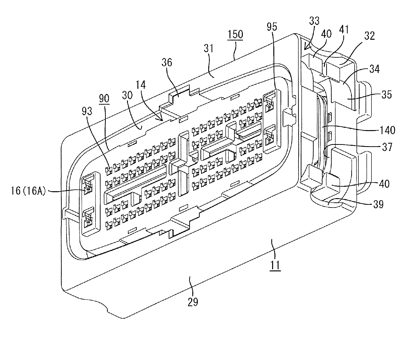
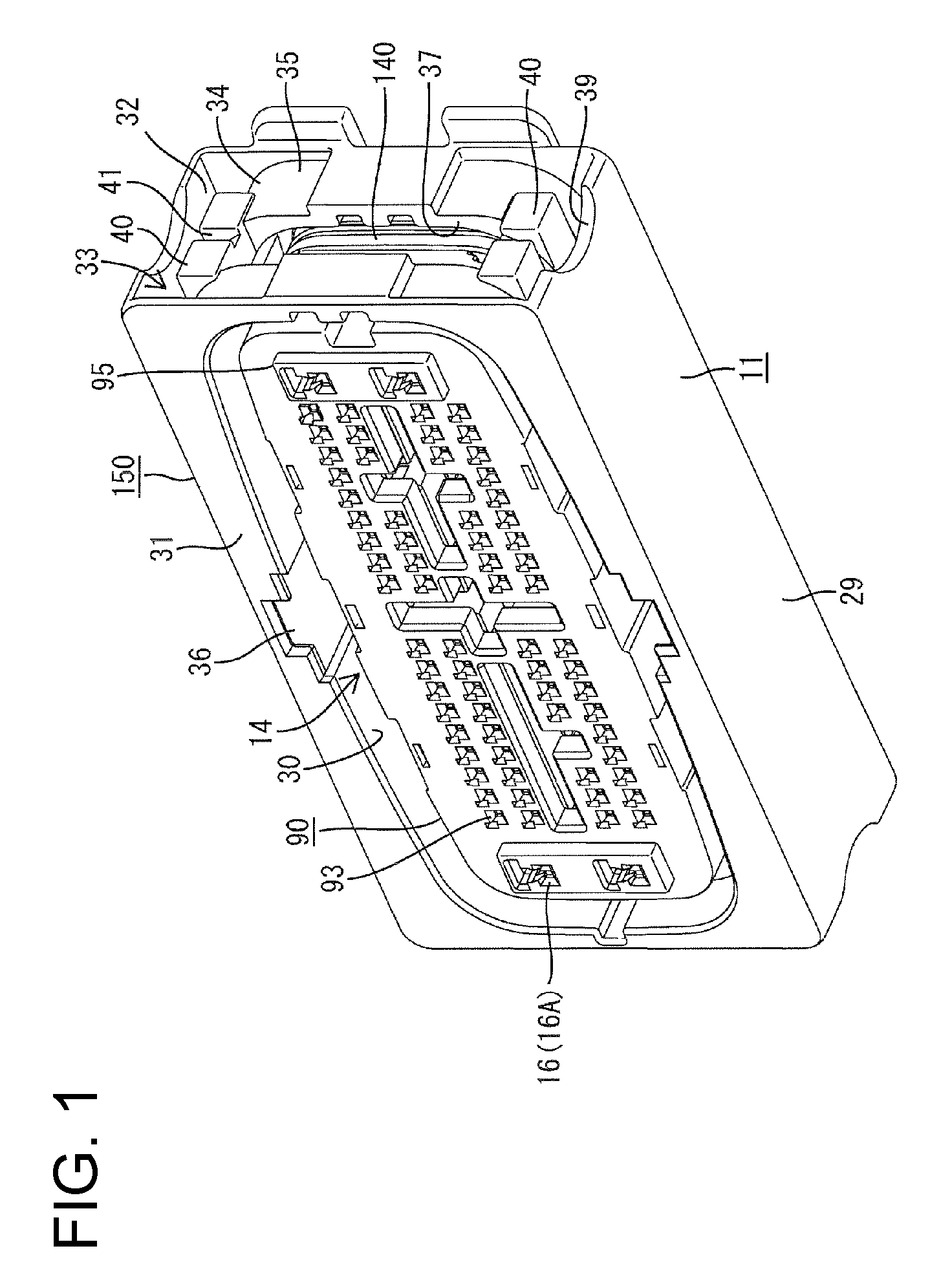
[0016]FIG. 1 is a perspective view of a connector housing according to the invention.

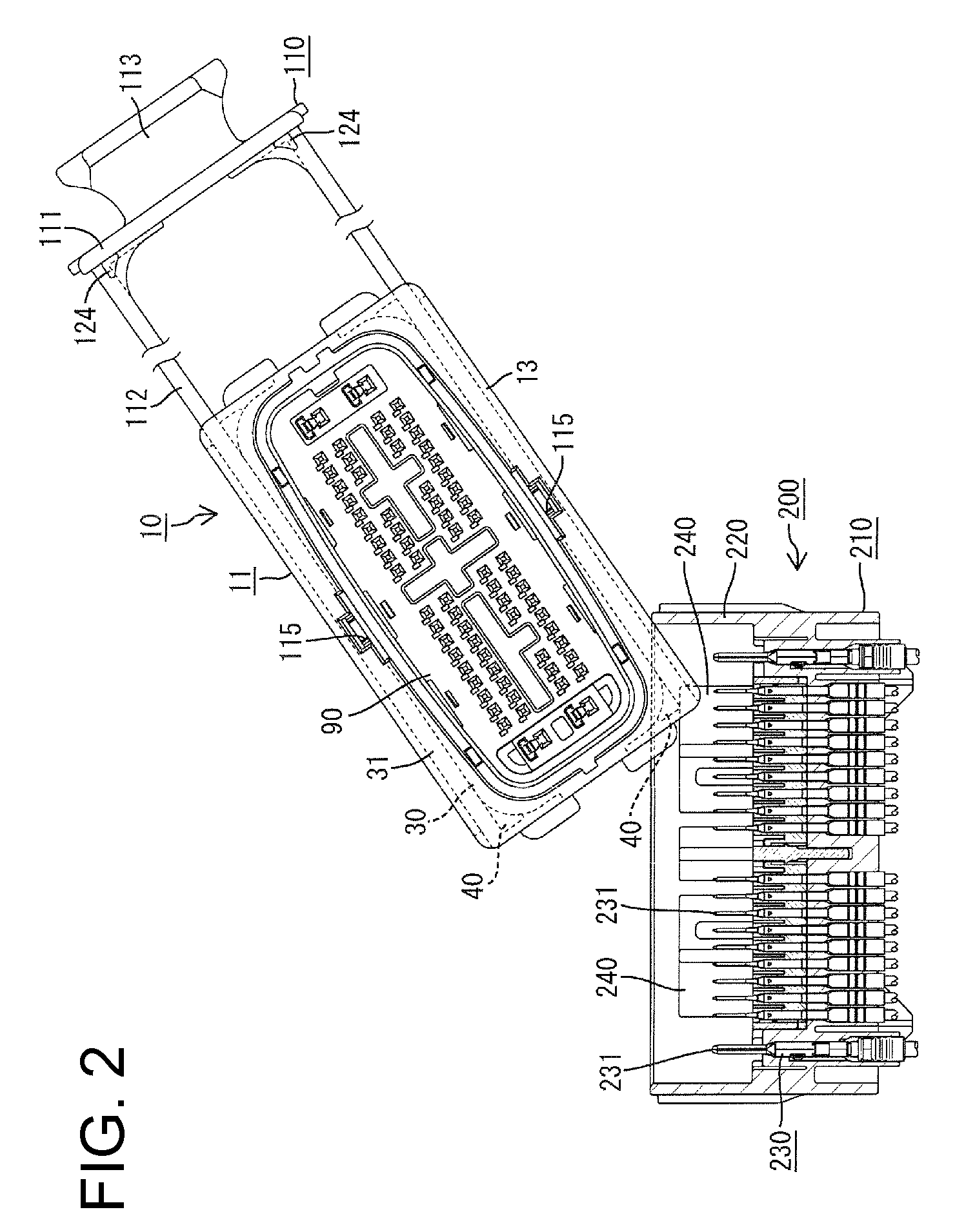
[0017]FIG. 2 is a front view showing a forced connection is prevented by a forced connection preventing portion when a housing is in an improper posture.

[0018]FIG. 3 is a reference diagram showing a state where forced connection occurs when the connector housing is in an improper posture.

[0019]FIG. 4 is a plan view partly in section showing follower pins in introducing portions of cam grooves and two housings left partly connected.

[0020]FIG. 5 is a plan view partly section showing the follower pins moved over protuberances and the partly connected state released.

[0021]FIG. 6 is a front view showing a state where a lance housing is fit into an accommodation recess of a housing main body.

[0022]FIG. 7 is an enlarged view of a part A of FIG. 6.

[0023]FIG. 8 is a front view of a connector.

[0024]FIG. 9 is a section along B-B of FIG. 8.

[0025]FIG. 10 is a vertical section of the housing main body.

[0026]FIG. ...

second embodiment

[0034]FIG. 19 is a plan view partly in section showing follower pins are in introducing portions of cam grooves and two housings left partly connected in a

[0035]FIG. 20 is a plan view partly section showing a state where the follower pins move over protuberances to release the partly connected state.

[0036]FIG. 21 is a front view of a mating housing with a follower pin.

third embodiment

[0037]FIG. 22 is a plan view partly section showing follower pins in introducing portions of cam grooves and two housings left partly connected in a

[0038]FIG. 23 is an enlarged front view of the follower pin.


PUM


Abstract

An accommodation recess (17) is formed in the front surface of a housing main body (11). A plate-like lance housing (70) including locking lances (19) for primarily locking terminal fittings (130) by resiliently deformably projecting at inner surfaces of terminal accommodation holes (71) is accommodated into the accommodation recess (17). A plate-like retainer (50) movable to a partly locked position for permitting the insertion of the terminal fittings (130) into the terminal accommodation holes (71) and to a fully locked position for secondarily locking the terminal fittings (130) is also accommodated into the accommodation recess (17). The rear surface of the lance housing (70) and the front surface of the retainer (50) are arranged in contact with each other.

Description

BACKGROUND OF THE INVENTION[0001]1. Field of the Invention[0002]The invention relates to a connector and to an assembling or mounting method therefor.[0003]2. Description of the Related Art[0004]Japanese Unexamined Patent Publication No. 2003-59590 discloses a connector provided with a retainer. This connector is provided with a housing including cavities, into which terminal fittings are insertable, and a retainer to be mounted through a side surface of the housing while crossing the cavities. Resiliently deformable locking lances project in the cavities of the housing before a retainer mounting portion, and the terminal fittings properly inserted into the cavities are primarily locked by these locking lances. Further, the retainer is movable to a partly locked position and to a fully locked position. At the partly locked position, retaining portions of the retainer are retracted from the cavities to permit the insertion of the terminal fittings into the cavities. At the fully lock...

Claims


Application Information

Patent Timeline
Patent Type & Authority Patents(United States)
IPC IPC(8): H01R13/40
CPCH01R13/4362H01R13/62911H01R13/62927
Inventor MASE, TSUYOSHITANAKA, TSUTOMU
Owner SUMITOMO WIRING SYST LTD
Why Eureka
Try Eureka