Kinematic rotating-tilting mechanism

a rotating tilting and kinematic technology, applied in the field of exercise equipment, can solve problems such as complexity, need preventive maintenance, and malfunctions

Inactive Publication Date: 2010-08-17
SHULTZ LARRY D
View PDF21 Cites 25 Cited by
  • Summary
  • Abstract
  • Description
  • Claims
  • Application Information

AI Technical Summary

Benefits of technology

[0021]To add to the utility of the KRTM, a resilient section is attached to the upper surface of the platform base. The resilient section is dimensioned to comfortably allow a person who is located on the upper surface of the resilient section to produce the required torque to operate the mechanism.
[0...

Problems solved by technology

These components, because of their complexity, are subject to malfunctions, require...

Method used


Image

  • Kinematic rotating-tilting mechanism
  • Kinematic rotating-tilting mechanism
  • Kinematic rotating-tilting mechanism

Examples


Embodiment Construction

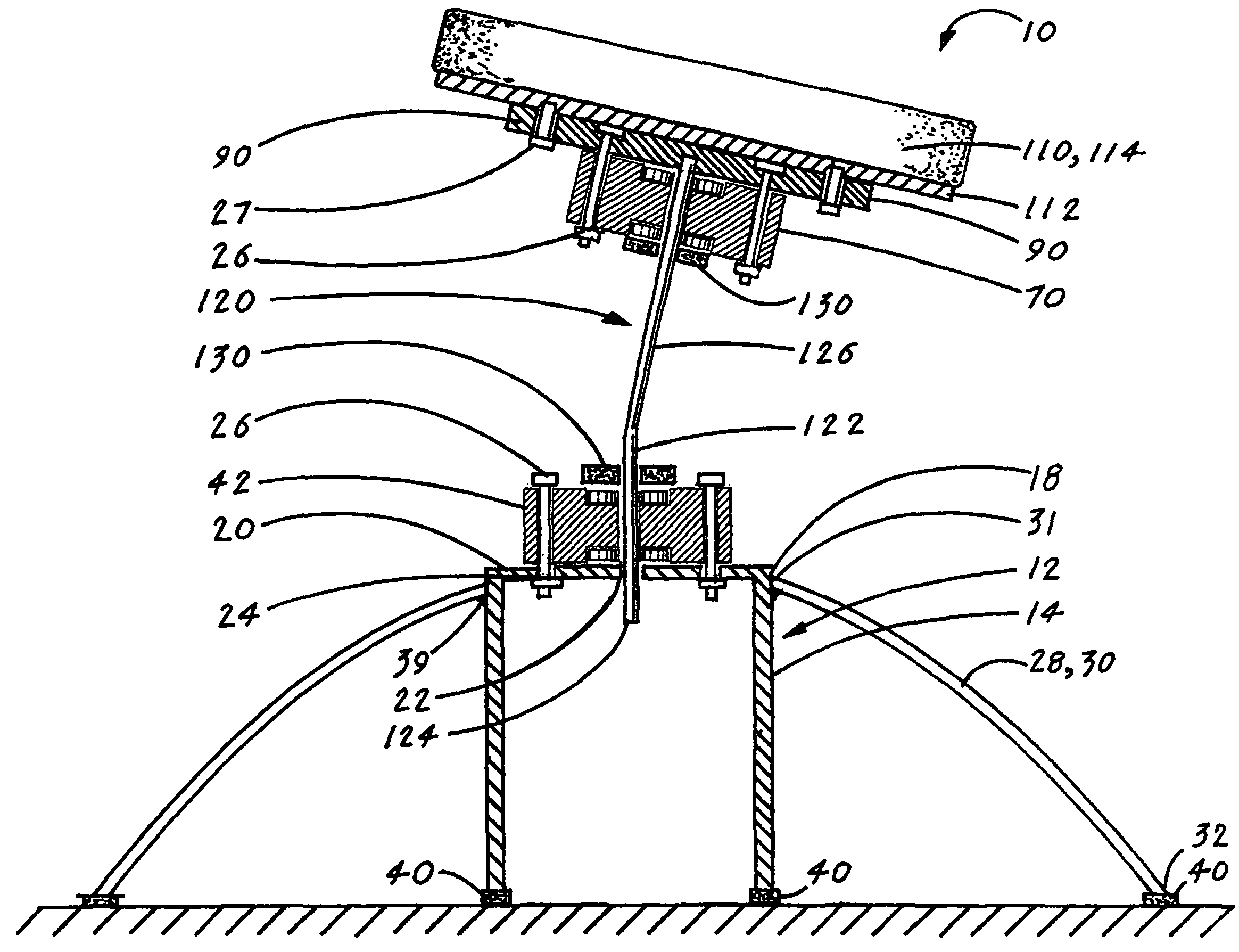
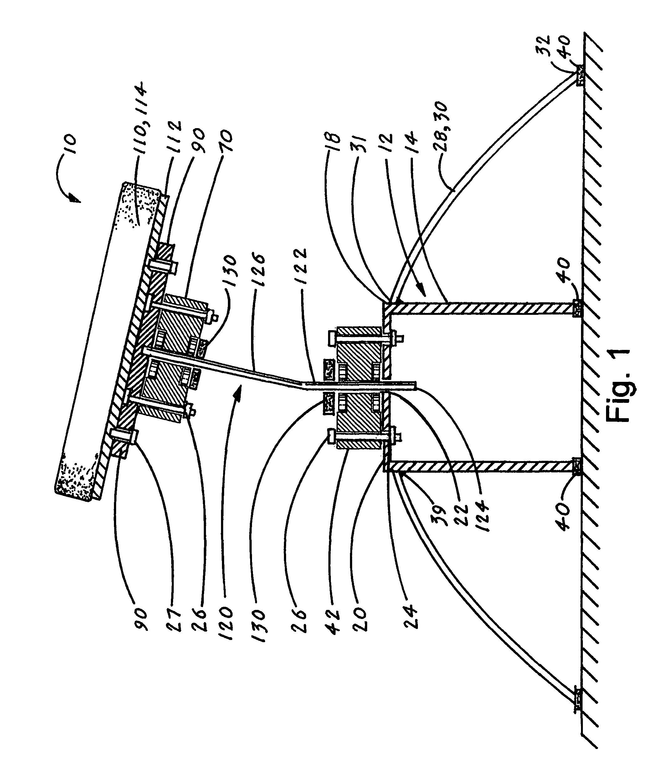
[0043]The best mode for carrying out the invention is presented in terms of a preferred embodiment for a kinematic rotating-tilting mechanism (hereinafter “KRTM 10”). The preferred embodiment of the KRTM 10, as shown in FIGS. 1-12, is comprised of the following six major elements: a housing 12, a housing flange assembly 42, a platform flange assembly 70, a platform base 90, a resilient section 110 and a shaft 120.

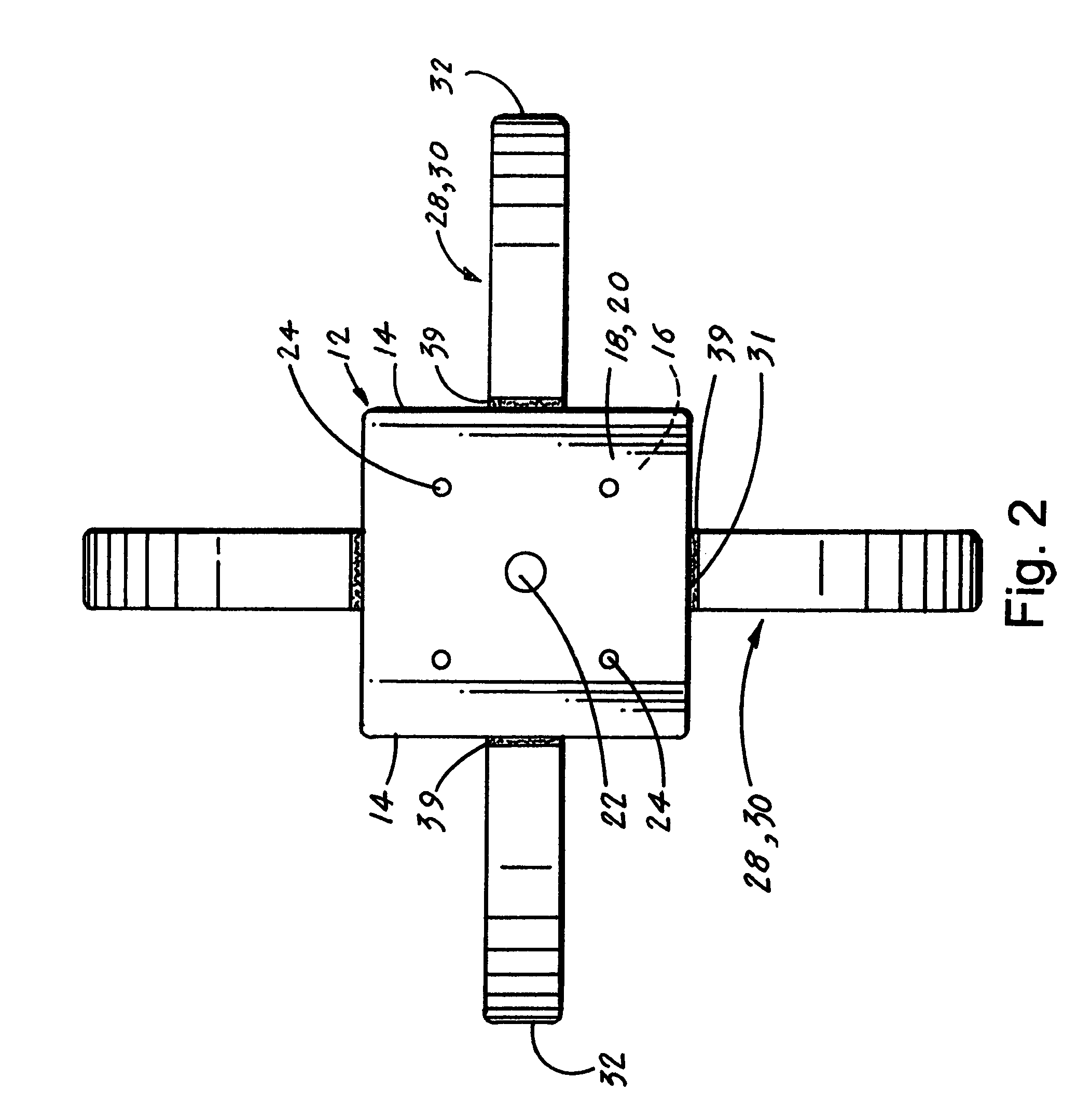
[0044]The housing 12, as shown in FIGS. 1-4, has enclosed sides 14, a lower end 16 and an upper end 18. The lower end 16, as best shown in FIG. 1, is open to facilitate the manufacturing process and also provides a means for attaching the housing assembly flange 42 and for adjusting the vertical level of the shaft 120. The upper end 18 of the housing 12 has an integrally attached cover 20, as shown in FIGS. 1 and 2. The cover 20 has a housing shaft bore 22 and a plurality of flange attachment bores 24, as shown in FIGS. 2 and 3.

[0045]As shown in FIGS. 1-4, the housing 12 is...


PUM


Abstract

A kinematic rotating-tilting mechanism (10) that consists of six major elements: a housing (12), a housing flange assembly (42), a platform flange assembly (70), a platform base (90), a resilient section (110) and an angled shaft (120). The housing (12) includes an upper end (18) having a cover (20) to which is attached the housing flange assembly (42), and attached to the lower surface (98) of the platform (90) is the platform flange assembly (70). The shaft (120) has a lower vertical section (122) that is rotatably attached to the housing flange assembly (42), and an upper angled section (126) that is rotatably attached to the platform flange assembly (70). The platform base (90) has an upper surface (96) to which is attached a resilient section (110). A person who is located on the resilient section (110) can produce torque by shifting their body weight. The torque causes the resilient section (110) to produce a combination rotating and tilting motion that promotes neuro-muscular stimulation, is relaxing, and aids in relieving stress.

Description

TECHNICAL FIELD[0001]The invention generally pertains to the field of exercising equipment, and more particularly to a kinematic rotating-tilting mechanism that allows a person located on a platform attached to the mechanism to perform exercising routines that produce torque, which causes the platform to simultaneously rotate and tilt.BACKGROUND ART[0002]The prior art is replete with various designs of equipment that allow a person to perform various exercising routines or to help a person relax and relieve stress. Some of the prior art equipment utilizes an articulated platform that is designed to mechanically or electrically produce a rotational or tilting motion or to produce a combination of both a rotational and a tilting motion.[0003]The rotational and / or tilting motions of the prior art equipment are typically achieved by utilizing a complex arrangement of components that are activated by means of mechanical devices or by an electric motor. These components, because of their ...

Claims


Application Information

Patent Timeline
IPC IPC(8): A63B21/00A61H1/02A63G1/00A63B21/008
CPCA63B22/14A63B22/18
Inventor SHULTZ, LARRY D.
Owner SHULTZ LARRY D
Why Eureka
Try Eureka