Attic vent

a venting device and vent structure technology, applied in ventilation systems, lighting and heating apparatuses, heating types, etc., can solve problems such as affecting ventilation, rain hitting the device, and bouncing up under the cap,

Active Publication Date: 2010-08-24
ROSS MFG
View PDF27 Cites 52 Cited by
  • Summary
  • Abstract
  • Description
  • Claims
  • Application Information

AI Technical Summary

Benefits of technology

[0019]The splash plate (i.e. the diverter) member includes a plurality of grooves to fit around the securing posts of the dome-shaped top member. The diverter effectively stops rain or snow from being drawn or splashed into the vented space. As previously described, the diverter may also be built into the base mold in a unitary or one-piece system as opposed to a device which slips over the base.

Problems solved by technology

However, such enclosures do typically require a passive vent to allow for air flow from the enclosure to outside atmosphere.
Experience has shown that wind traveling along the sloped roof will often drive snow up under the cap and through the vent structure into the attic.
This problem can be exacerbated in cases where the intakes beneath the eaves become blocked, are improperly installed, do not exist, or have inadequate openings for free flow of air into the ventilated space.
Though devices such as the McKee device are generally effective in blocking entry of rain into the attic, it has also been found that they can leak during extreme weather conditions such as torrential rain.
First, torrential rains are often accompanied by high winds which can drive rain into the vent structure in the same way described above with respect to snow.
Second, because there is a great deal of rain falling very hard, rain can strike the device, bounce up under the cap, and enter the vent structure.
Another issue with respect to roof vents is their use in conjunction with roofing materials such as shingles, shakes or tiles.
Also, the vent structure of McKee includes areas below the vent structure which tend to trap moisture, thus creating a pool which may encourage mildew or other unwanted growth.

Method used


Image

  • Attic vent
  • Attic vent
  • Attic vent

Examples


Embodiment Construction

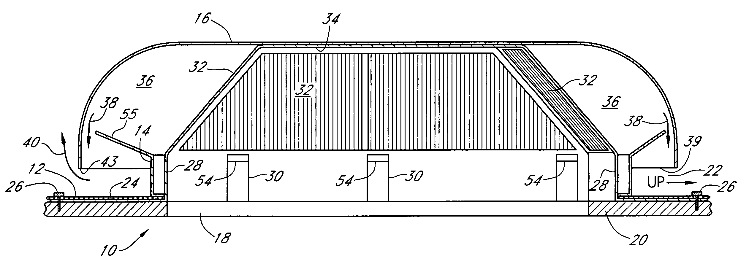
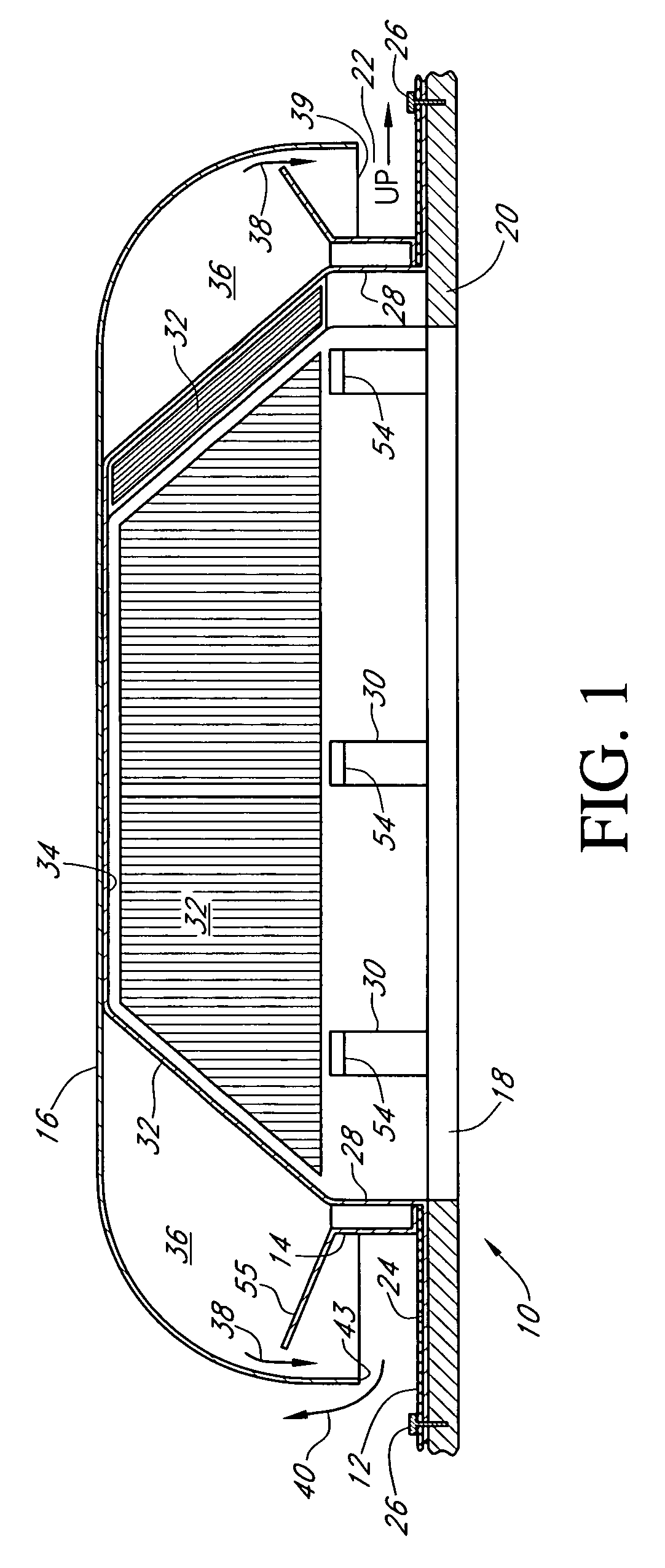
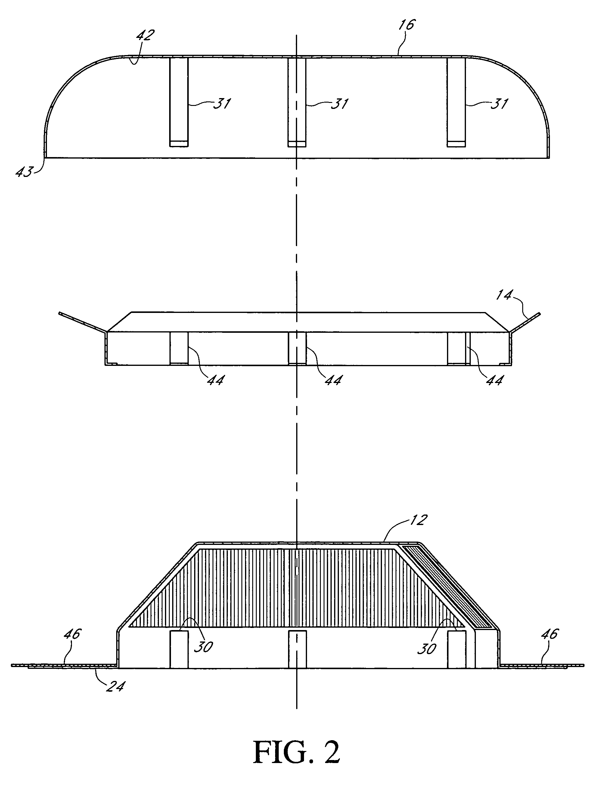
[0029]Referring first to FIGS. 1 and 2, there is shown a sectional view of the passive vent 10 of this invention in an assembled condition (FIG. 1) and in an exploded view (FIG. 2). The vent 10 comprises primarily a bottom base component 12, an intermediate diverter component 14, and a top dome-shaped component 16. The entire vent, once installed, fits in a water-tight seal over an opening 18 in a roof 20 such as, for example, over an attic or other similar enclosure which requires venting. If the vent 10 is installed on a sloping roof, such as is common on a residence, then the vent 10 includes a preferred orientation so that a particular portion of the vent is directed up the slope of the roof, as indicated by a legend marker 22 which is preferably molded into the base component 12 to assist an installer in properly orienting the vent 10.

[0030]The base component 12 includes a wide, flat mounting plate or flange 24. The mounting plate 24 extends beyond the dome-shaped component 16 ...


PUM


Abstract

A passive venting device for venting enclosures comprising a base member, an intermediate splash member including a diverter, and a top, dome-shaped member. In a preferred embodiment, the diverter may be molded as a single unit of manufacture with the base member. The venting device allows air and other gases to escape from within an enclosure to be vented while preventing the intrusion of moisture, such as rain or snow, into the enclosure.

Description

[0001]This is a continuation of application Ser. No. 11 / 306,276 filed Dec. 21, 2005, entitled Attic Vent (now U.S. Pat. No. 7,544,124).FIELD OF THE INVENTION[0002]This invention relates generally to the field of venting devices. In particular, it relates to a passive vents for mounting on the slanted roof of a residential dwelling or the like. The vent may as easily be mounted onto a flat roof, as desired.BACKGROUND OF THE INVENTION[0003]As described in U.S. Pat. No. 6,767,281 to McKee (McKee '281), most buildings and enclosures where human activity takes place require some type of venting. The type of venting device used depends on the kind of enclosure to be vented. For example, bathrooms with showers typically have active vents with fans to vent steam to the outdoors. Kitchens, particularly in restaurants and hotels, similarly have powered vents for removing smoke, steam and other matter.[0004]Other types of enclosures, such as attics, do not require active venting. However, such...

Claims


Application Information

Patent Timeline
Patent Type & Authority Patents(United States)
IPC IPC(8): F24F7/02F24F13/08F24F13/20
CPCF24F7/02
Inventor POLSTON, SCOTT
Owner ROSS MFG
Why Eureka
Try Eureka