Method and apparatus for parallett and ballet bar fixture

a technology of parallett and bar fixture, which is applied in the field of gymnastics, dance and general exercise methods and apparatus, can solve the problems of long pipe length, if hollow, and is too flexible, and achieve the effects of safe support, rigidity, strength and user safety

Inactive Publication Date: 2010-08-24
GOODWIN III WILLIAM H +1
View PDF7 Cites 24 Cited by
  • Summary
  • Abstract
  • Description
  • Claims
  • Application Information

AI Technical Summary

Benefits of technology

[0014]In the invention, each five sided triangular shaped end cap has a flat base surface that is intended to sit flush against a flat surface. Blind cavities are formed in each end cap. Such cavities define a surrounding peripheral wall which includes a grooved base and a pair of vertical mounting support ribs which support a single top blind opening for each end cap. The outer surface area of each end cap is continuous, smooth and essentially flat and is chosen with a thickness sufficient to safely support the highly skilled gymnast—and novices as well—regardless of size, weight or vigorous bar activities. A chosen radius of curvature for the wall thickness and exposed inner peripheral wall supplies rigidity, strength and user safety for a PVC system of this parallett invention.
[0017]Competitive or professional gymnastic equipment provides a familiar feel of some give and resilience in response to moves being practiced by the user. Such characteristics are accurately simulated by the PVC sections of my invention. The length and strength of a selected Schedule PVC pipe controls the amount of give and resilience. Additionally, the stiffness of the inner filler pole section may, if desired, also be varied to custom control the give and resilience for a particular user.
[0027]Inside blind cavities and smooth outside end caps surface for safety and improved appearance.

Problems solved by technology

Longer pipe lengths, if hollow, will be too flexible.

Method used


Image

  • Method and apparatus for parallett and ballet bar fixture
  • Method and apparatus for parallett and ballet bar fixture
  • Method and apparatus for parallett and ballet bar fixture

Examples


Embodiment Construction

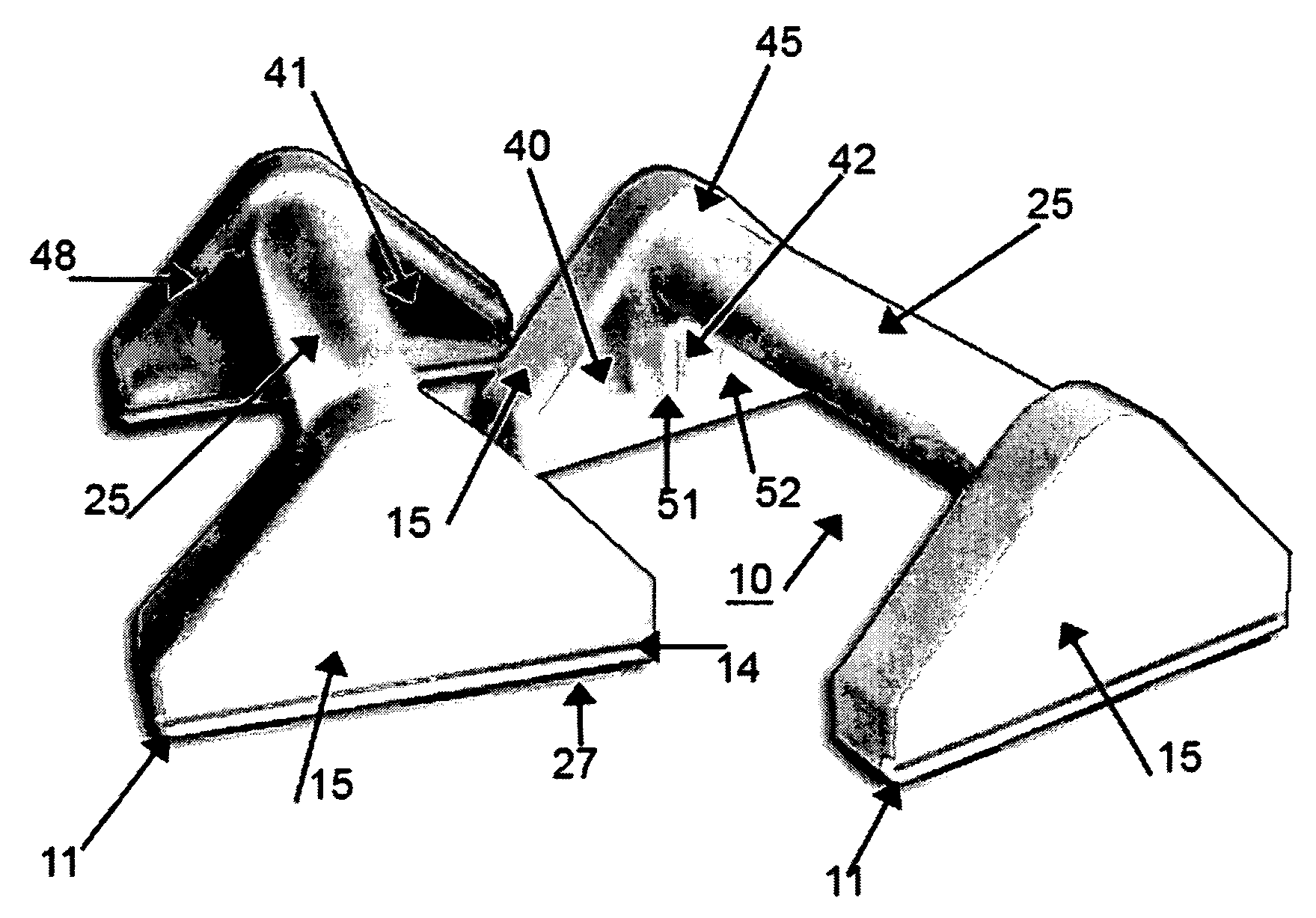
[0034]FIG. 1 depicts a pair of paralletts in accordance with the principle of this invention. Each parallett 10 comprises a pair of opposing end support caps 15 having bridged there across a single bar 25. For floor based exercises such paralletts rest upon the floor. Right and left handholds are provided by the pair of bars 25 which are held horizontal to the floor and spaced a few inches away from the surface of the floor.

[0035]End support caps 10 each have a flat base surface 11 that is intended to sit flush against the floor and hold a pressure sensitive non-skid bottom strip 27. These end support caps are smooth on the outside triangular surface, while the inside surfaces have formed therein a series of cavities 40, 41, 42 and 45. These cavities are best shown in the background view of the inside surface of the end caps 15 of FIG. 1. Such cavities are defined by wall and rib sections that terminate around a circular blind opening 45 located at the top of each triangular end cap...


PUM


Abstract

Triangular shaped smooth outside and cavities inside with a PVC parallett / ballet bar supported by blind holes at the top of a pair of triangular end caps. End cap bar opening has a ridged inside dimension that is tapered slightly from the inside to the outside surface areas. Tapering by ridged ramps located inside that bar opening, allows the end caps and bar to forcibly seize unto each other with a firm bond requiring no further fastening agent. Bar may include a filler pole for rigidity especially in longer length devices. End caps likewise seize and hold both a PVC bar and / or the PVC / filler insert combination.

Description

PREVIOUS FILING INFORMATION[0001]On Dec. 15, 2003 the United States Patent Office received a copy of—and assigned Ser. No. 60 / 529,674 to—a Provisional Patent Application (PPA) filed by the same inventors hereof. That PPA is incorporated herein by this reference as though set out here in full. Additionally, the PPA is being supplemented by this Regular Patent Application (RPA). Applicant expressly reserves all rights and privileges flowing from the PPA and its earlier official filing date and contents thereof. This RPA follows, and it is supported by the PPA.BACKGROUND OF THE INVENTIONField of the Invention[0002]This invention relates to gymnastics, dance and general exercise methods and apparatus. More specifically, the field of this invention relates to novel end caps for receiving a bar in the form of a pipe or PVC section suitable for use in doing handstands, pirouette, ballet and similar type exercise activities. Additionally the field of this invention relates to a non-gymnasiu...

Claims


Application Information

Patent Timeline
Patent Type & Authority Patents(United States)
IPC IPC(8): A63B4/00A63B1/00
CPCA63B1/00A63B4/00A63B23/1218A63B23/1236A63B2021/169A63B2244/22A63B21/169
Inventor GOODWIN, III, WILLIAM H.GOODWIN, JODY R.
Owner GOODWIN III WILLIAM H
Why Eureka
Try Eureka