AI technical title is built by Patsnap AI team. It summarizes the technical point description of the patent document.
a technology of pump apparatus and pump body, which is applied in the direction of machines/engines, positive displacement liquid engines, eye treatment, etc., can solve the problems of long-term damage to surrounding tissue, unreliable or frequent maintenance, and lack of reliable power sour
Inactive Publication Date: 2010-08-24
SOLTANPOUR DAVID P
View PDF2 Cites 14 Cited by
Summary
Abstract
Description
Claims
Application Information
AI Technical Summary
This helps you quickly interpret patents by identifying the three key elements:
Problems solved by technology
Method used
Benefits of technology
Problems solved by technology
One problem with these devices is the lack of a reliable, long term power source.
While these systems are somewhat effective, they tend to suffer from the drawback in that they are unreliable or require frequent maintenance which always involves a fairly invasive procedure.
Failure to properly maintain the devices can result in long term damage to surrounding tissue especially in the case of pumps used to control glaucoma.
Power sources for these implantable pumps have to be either implantable batteries that need to be replaced after a while or transcutaneously charged every once in a while or inductive energy sources which tend to be cumbersome because an inductive energy receiving armature needs to implanted alongside with them and an inductive energy source needs to be brought close to them to induce current and subsequently energize the device.
The pump is programmable, but the patent does not disclose which aspects of the pump operation can be controlled.
Method used
Image
Click on the blue label to locate the original text in one second.
Reading with bidirectional positioning of images and text.
Examples
Embodiment Construction
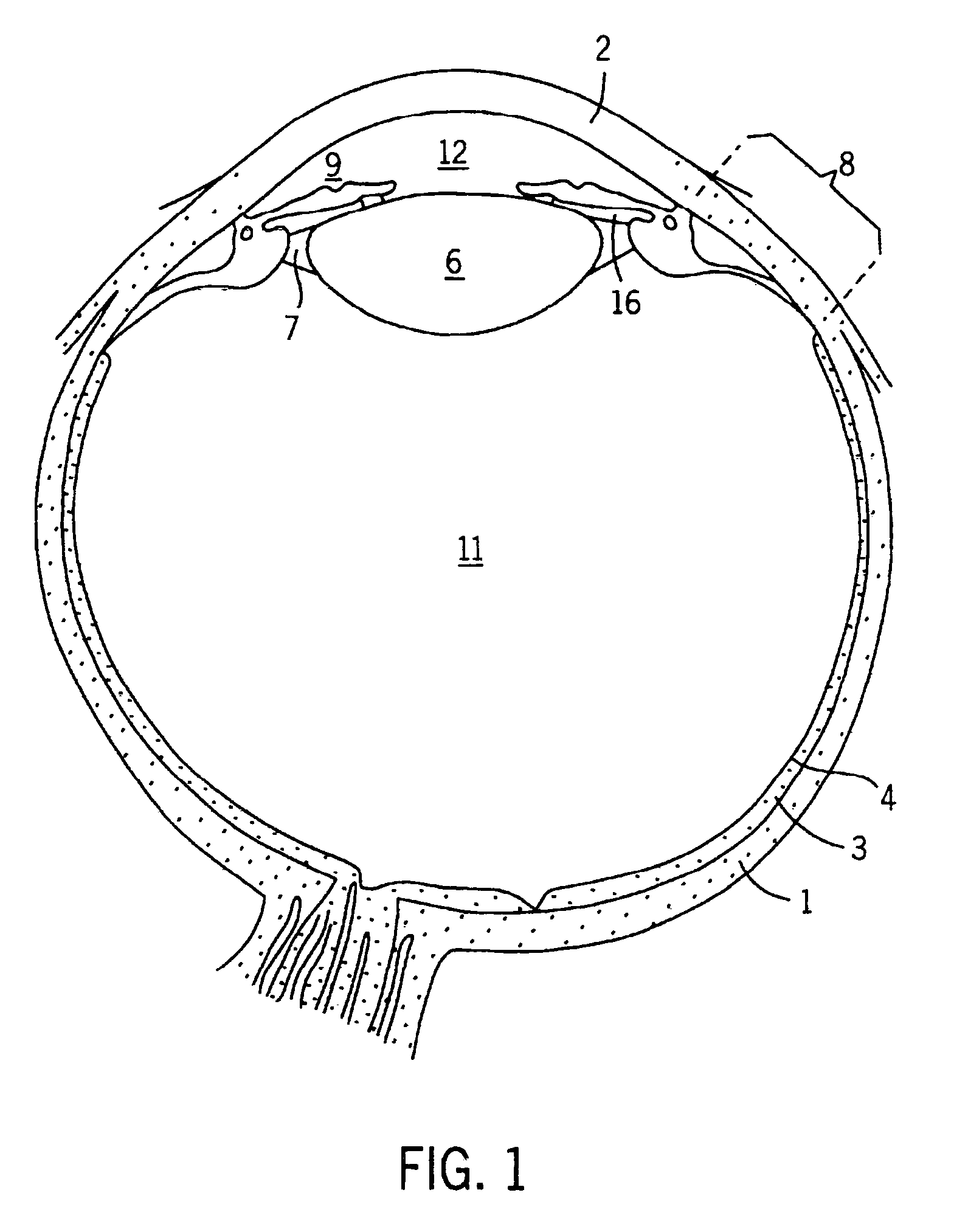
[0041]The major anatomical structures of the eye are shown in FIG. 1. The eye is surrounded by an outer protective layer, the sclera 1. The anterior portion of the sclera 1, the cornea 2, is modified to allow light rays to enter the eye. The choroid 3 resides within the sclera 1 and comprises vasculature which nourishes most of the structures of the eyeball. The posterior portion of the choroid 3 is lined by the retina 4. The retina 4 is composed of the neural tissue containing the receptor cells that receive and process the incoming light rays.
[0042]FIG. 1 also illustrates several other structures of the eye, particularly those areas to be affected by the pump assembly of the invention, generally indicated by the numeral 10. The transparent, biconvex lens 6, one of the refractive media of the eye, is secured by the lens ligament 7 to the ciliary body 8. The ciliary body 8 is the thickened anterior portion of the choroid 3. The iris 9, the “colored” portion of the eye, lies in front...
PUM
Abstract
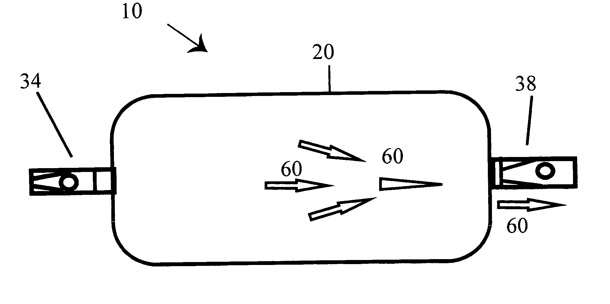
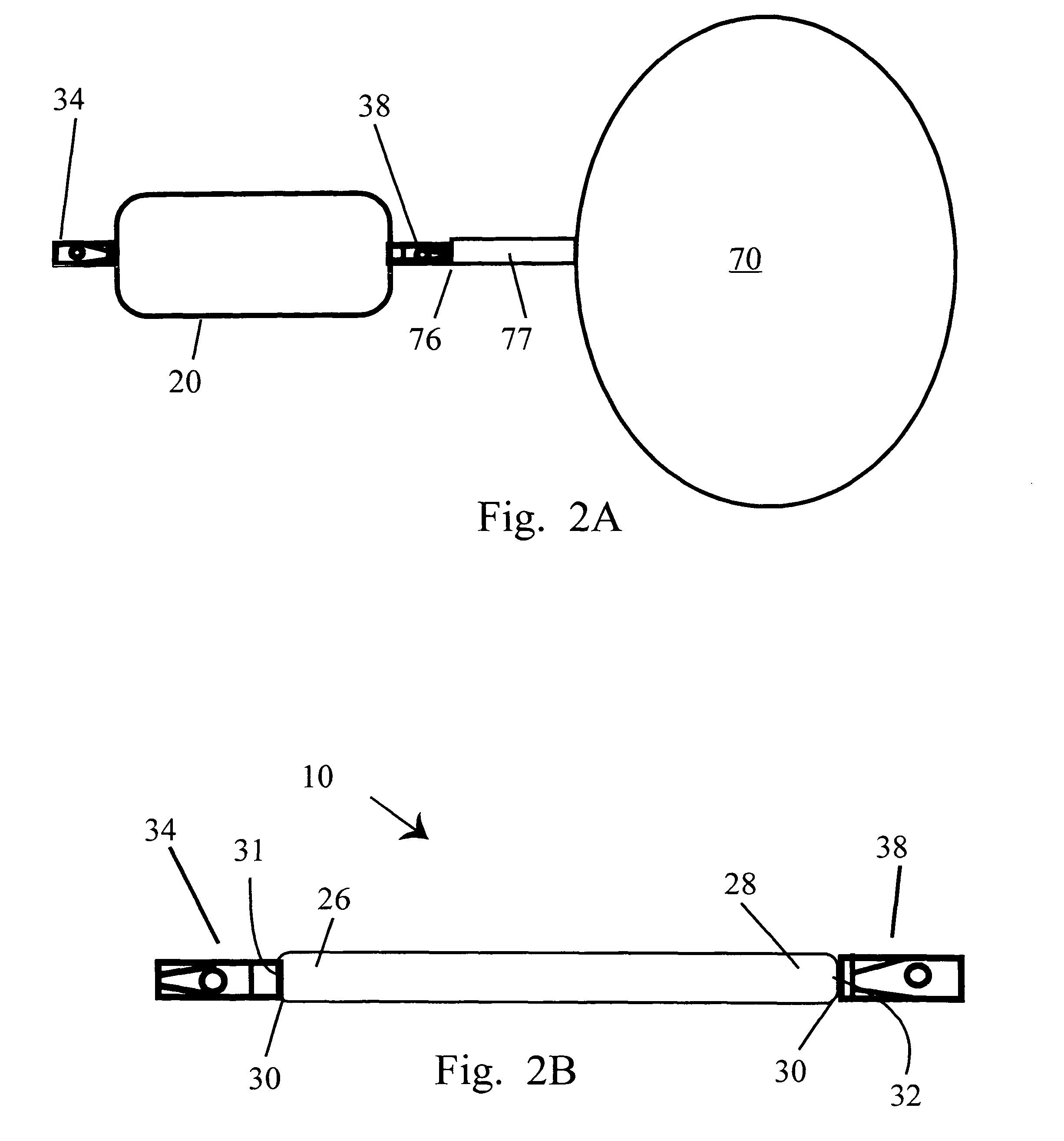
An implantable, miniature pump assembly having a flexible elastic bladder actuating assembly. The bladder, in the non-flexed state, has an elongated, substantially rectangular profile, with a predetermined internal volume or capacity. Influent and effluent conduits extend in opposite directions from respective end portions of the bladder. Each of the conduits include one way valves disposed therein to limit fluid flow to a single direction into and through the bladder. Contraction and expansion of the bladder by means of energy harvested from the dynamic environment in which it is implanted in response to ambient random dynamic motion creates alternating pressure and vacuum within the bladder, alternately drawing fluid into the bladder through the influent conduit, and forcing fluid from the bladder via the effluent conduit. The bladder pump assembly harvests its operational energy from the random dynamic motion of the surrounding organs and tissues and therefore does not require an internal or external power source.
Description
CROSS REFERENCE TO RELATED APPLICATIONS[0001]This application is a continuation in part of application Ser. No. 10 / 733,090, filed on Dec. 12, 2003 now abandoned; which is a continuation in part of application Ser. No. 09 / 841,191, filed on Apr. 25, 2001, now U.S. Pat. No. 6,682,500; which is a continuation in part of application Ser. No. 09 / 586,962, filed on Jun. 5, 2000, now U.S. Pat. No. 6,589,198, which is a continuation in part of application Ser. No. 09 / 015,759, filed on Jan. 29, 1998, now U.S. Pat. No. 6,168,575.BACKGROUND OF THE INVENTION[0002]1. Field of the Invention[0003]The present invention relates to pump assemblies. More specifically, it relates to self-powered microminiature bladder pumps which may be used as bio-compatible medical implants for controlling diseases such as glaucoma and hydrocephalus, and to effect drug delivery.[0004]2. Description of the Prior Art[0005]Mechanical and electro-mechanical medical implants are well known, and, depending upon the type, hav...
Claims
Application Information
Patent Timeline
Application Date:The date an application was filed.
Publication Date:The date a patent or application was officially published.
First Publication Date:The earliest publication date of a patent with the same application number.
Issue Date:Publication date of the patent grant document.
PCT Entry Date:The Entry date of PCT National Phase.
Estimated Expiry Date:The statutory expiry date of a patent right according to the Patent Law, and it is the longest term of protection that the patent right can achieve without the termination of the patent right due to other reasons(Term extension factor has been taken into account ).
Invalid Date:Actual expiry date is based on effective date or publication date of legal transaction data of invalid patent.

