Method and apparatus for measuring and estimating subject motion in variable signal reception environments

a variable signal reception and subject motion technology, applied in distance measurement, navigation instruments, instruments, etc., can solve the problems of inability to maintain consistent stride, inability to accurately estimate the speed and distance covered, and failure to gain widespread acceptance of portable pedometers, etc., to achieve easy viewability of speed and distance measurement and light weight

Inactive Publication Date: 2010-09-30
MARIANO THOMAS +1
View PDF25 Cites 36 Cited by
  • Summary
  • Abstract
  • Description
  • Claims
  • Application Information

AI Technical Summary

Benefits of technology

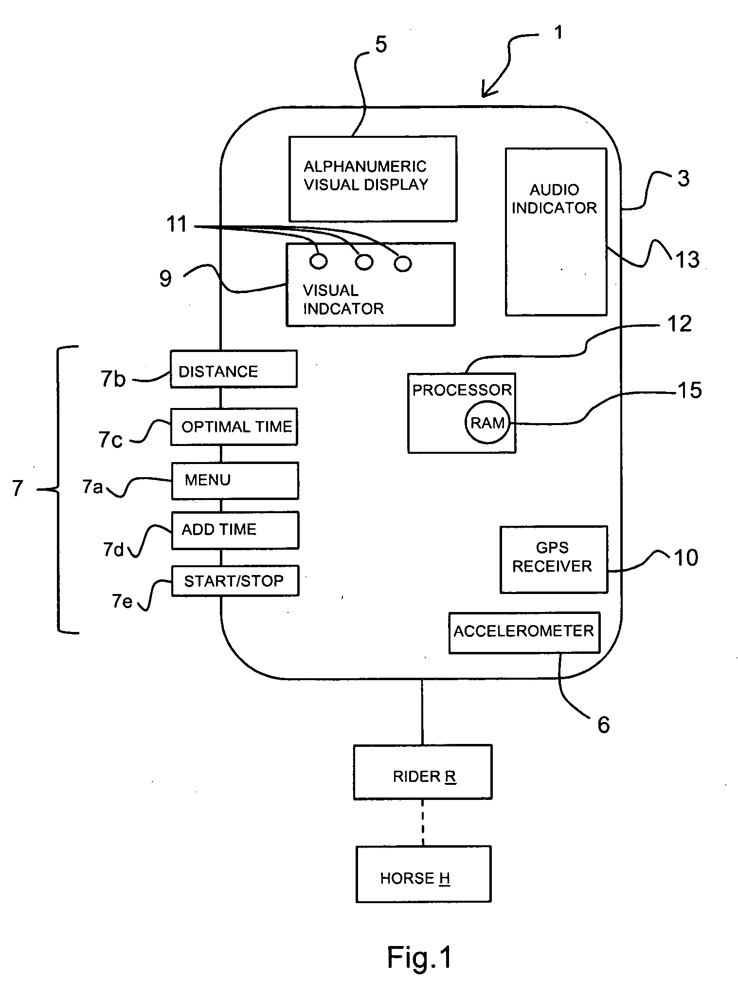
[0014]It is an object of the present invention to provide a light weight, easily viewable speed and distance measurement device for athletes.
[0015]It is another object of the present invention to provide the speed and distance measurement device with a GPS system which interfaces with the device to provide accurate location data for performing calculations to attain highly accurate speed and distance measurements.
[0017]A still further object of the present invention is to provide an easily viewable or audible signal which indicates whether the user's current condition and location are within a desired range of predefined parameters.
[0020]The present embodiments of a speed and distance measurement device are advantageous over the prior art because of the increased accuracy of the device compared to the known speed and distance measuring devices even where GPS signals are not received. Speed is a critical safety factor in such eventing and cross-country competitions. It is difficult for a rider to judge their own speed throughout, and at any given point in time, during an event. Where a rider is aware of their accurate position and speed, the rider is more easily able to consistently determine a safe and competitive speed at which to negotiate the course. In this way where the rider has a better idea of their speed and the distance covered, or left to be covered, the safety as well as the competitiveness of the horse and rider is improved.
[0021]A speed and measurement device worn by the rider that measures speed and distance is a novel solution to the problems discussed above. At any and all times during the cross-country course the rider would be aware of the necessity to speed up, or slow down so as to complete the competition as close as possible to the optimum time. Particularly advantageous is the aspect of the present invention where, as the rider comes closer to the finish line the rider can fine-tune the speed to attain the optimal time. Another aspect of the present invention is the ability of the speed and distance measurement device to show the horse and riders' deviation from the desired speed. This would be important for a competitor, either in training or in an event to attain a feel for various speeds. This would help the rider with other equestrian events as well such as racing, endurance riding, etc.

Problems solved by technology

The pedometer senses the vertical motion of the athlete corresponding to the steps or strides of the athlete however the accuracy of such known pedometer devices is less than desirable.
Such portable pedometers have failed to gain widespread acceptance mainly because the results obtained therefrom are typically inaccurate.
The inaccuracy results from the fact that the athlete's or animals stride must be consistent in order to return an accurate distance and speed.
Obviously and by way of example in cross-country running or equestrian cross-country terrain is often extremely varied and a consistent stride cannot be maintained.
Also, an athlete's stride may change according to their health and fitness over time as well as the particular duration of the athletic event so that it is very difficult to attain a truly consistent stride for purposes of accurate speed and distance measurement.
Where the actual stride is different from the theoretical stride the inaccuracies accumulate due to such stride variation and therefore such devices return less than adequate results of distance and speed measurements.
Although accelerometers provide a mechanism for determining the user step size, accelerometer measurements are not always accurate or consistent.
However, the GPS receiver is not always operable when GPS satellite signals are blocked by heavily wooded areas, building structures, terrain impediments such as cliffs or mountains, etc.
As discussed above the pedometer and / or accelerometer is not consistently accurate, causing error to accumulate in the acquired data of the pedometer and / or accelerometer without the location determining data components of the location determining system.
This assumes that the user traveled in a straight line while the GPS signal was not present and this assumption will not always be accurate.
GPS systems alone are not accurate enough for some applications.
GPS systems typically have an accuracy of plus or minus 10 meters and do not lend themselves to calculation of instantaneous speed because each position reading by the system has error of + / −10 meters the distance calculation between two points has therefore a possible error of + / −20 meters.
Successive calculations solely by the GPS may build and compound these errors in any calculation of speed.
However there is no way of knowing how far along in the course they are i.e. their relative course position, compared to where they should be, i.e. their desired course position, to complete the course within, or as close to the optimum time as possible.
By the time a rider comes within sight of the finish line they could be too far behind to catch up, or are too fast, and cannot according to the rules stop, or slow down to avoid time penalties.
As such, the systems provide no method or mechanism for calibrating the pedometer and combining this calibration with the GPS calculations so that the measurement system as a whole does not calculate a more accurate distance traveled better than the GPS can do alone.
Instead the systems merely correct accumulated position error once GPS satellite signals are accessible which does not update and allow the pedometer to accurately determine the distance traveled and future times when GPS signals are again inaccessible.

Method used


Image

  • Method and apparatus for measuring and estimating subject motion in variable signal reception environments
  • Method and apparatus for measuring and estimating subject motion in variable signal reception environments
  • Method and apparatus for measuring and estimating subject motion in variable signal reception environments

Examples


Embodiment Construction

[0033]Before explaining the present embodiments in detail, it is to be understood that the embodiments are not limited to the particular descriptions and that it can be practiced or carried out in various ways. In the following description, at least one embodiment of the present invention will be described as a software program. Those skilled in the art will readily recognize that the equivalent of such software may also be constructed in hardware. Because data manipulation algorithms and systems are well known, the present description will be directed in particular to algorithms and systems forming part of, or cooperating more directly with, the method in accordance with the present invention. Other aspects of such algorithms and systems, and hardware and / or software for producing and otherwise processing the data signals involved therewith, not specifically shown or described herein may be selected from such systems, algorithms, components, and elements known in the art.

[0034]The ...


PUM


Abstract

A dynamic motion and distance measuring device for estimating and measuring speed and distance covered by a subject engaged in an athletic endeavor and more particularly to measuring and estimating the speed and distance and providing a relative indication of a measured speed and distance to an optimal speed and distance and / or time including finish time of the subject engaged in an athletic event, even where the event is occurring in changing environment or terrain conditions where remote data collection and signal reception is inconsistent and variable.

Description

FIELD OF THE INVENTION[0001]The present embodiments of a dynamic motion and distance measuring device relate to a method and apparatus for estimating and measuring speed and distance covered by a subject engaged in an athletic endeavor and more particularly to measuring and estimating the speed and distance and providing a relative indication of a measured speed and distance to an optimal speed and distance and / or time including finish time of the subject engaged in an athletic event, even where the event is occurring in changing environment or terrain conditions where remote data collection and signal reception is inconsistent and variable.BACKGROUND OF THE INVENTION[0002]Although the following discussion of the background will focus on the use of the below described speed and distance measuring devices in equestrian events, it is to be appreciated that the use and applications of the presently described speed and distance measurement device extends beyond equestrian athletic event...

Claims


Application Information

Patent Timeline
Patent Type & Authority Applications(United States)
IPC IPC(8): G01P21/00G01P15/00G01P7/00G01B21/16
CPCA63K3/00G01C22/006G01C21/165G01B21/16A01K15/027
Inventor MARIANO, THOMASMARIANO, MARILYN
Owner MARIANO THOMAS
Why Eureka
Try Eureka