Distal protection device and method

a protection device and shielding device technology, applied in the field of shielding devices, can solve the problems of restricted blood flow in the lumen of the blood vessel, thrombosis can be particularly problematic, and certain problems are encountered

Inactive Publication Date: 2010-08-24
BOSTON SCI SCIMED INC
View PDF146 Cites 180 Cited by
  • Summary
  • Abstract
  • Description
  • Claims
  • Application Information

AI Technical Summary

Problems solved by technology

Also, the stenosis can be formed of a thrombus material which is typically much softer than an atheroma, but can nonetheless cause restricted blood flow in the lumen of the blood vessel.
Thrombus formation can be particularly problematic in a saphenous vein graft (SVG).
Certain problems are encountered during thrombectomy and atherectomy.
If the debris flows distally, it can occlude distal vasculature and cause significant problems.
If it flows proximally, it can enter the circulatory system and form a clot in the neural vasculature, or in the lungs, both of which are highly undesirable.
However, this technique has certain problems.
For instance, it is difficult to control the size of the fragments of the stenotic lesion which are severed.
Therefore, larger fragments can be severed accidentally.
Also, since thrombus is much softer than an atheroma, it, tends to break up easier when mechanically engaged by a cutting instrument.
Therefore, at the moment that the thrombus is mechanically engaged, there is a danger that it can be dislodged in large fragments which would occlude the vasculature.
However, it may be necessary to pull quite a high vacuum in order to remove all of the pieces severed from the stenosis.
Further, when a high vacuum is used, this can tend to cause the vasculature to collapse.
Problems are also associated with this technique.
For example, delivery of such devices in a low profile, pre-deployment configuration can be difficult.
Further, some devices include complex and cumbersome actuation mechanisms.
Also, retrieving such capture devices, after they have captured emboli, can be difficult as well.

Method used


Image

  • Distal protection device and method
  • Distal protection device and method
  • Distal protection device and method

Examples


Embodiment Construction

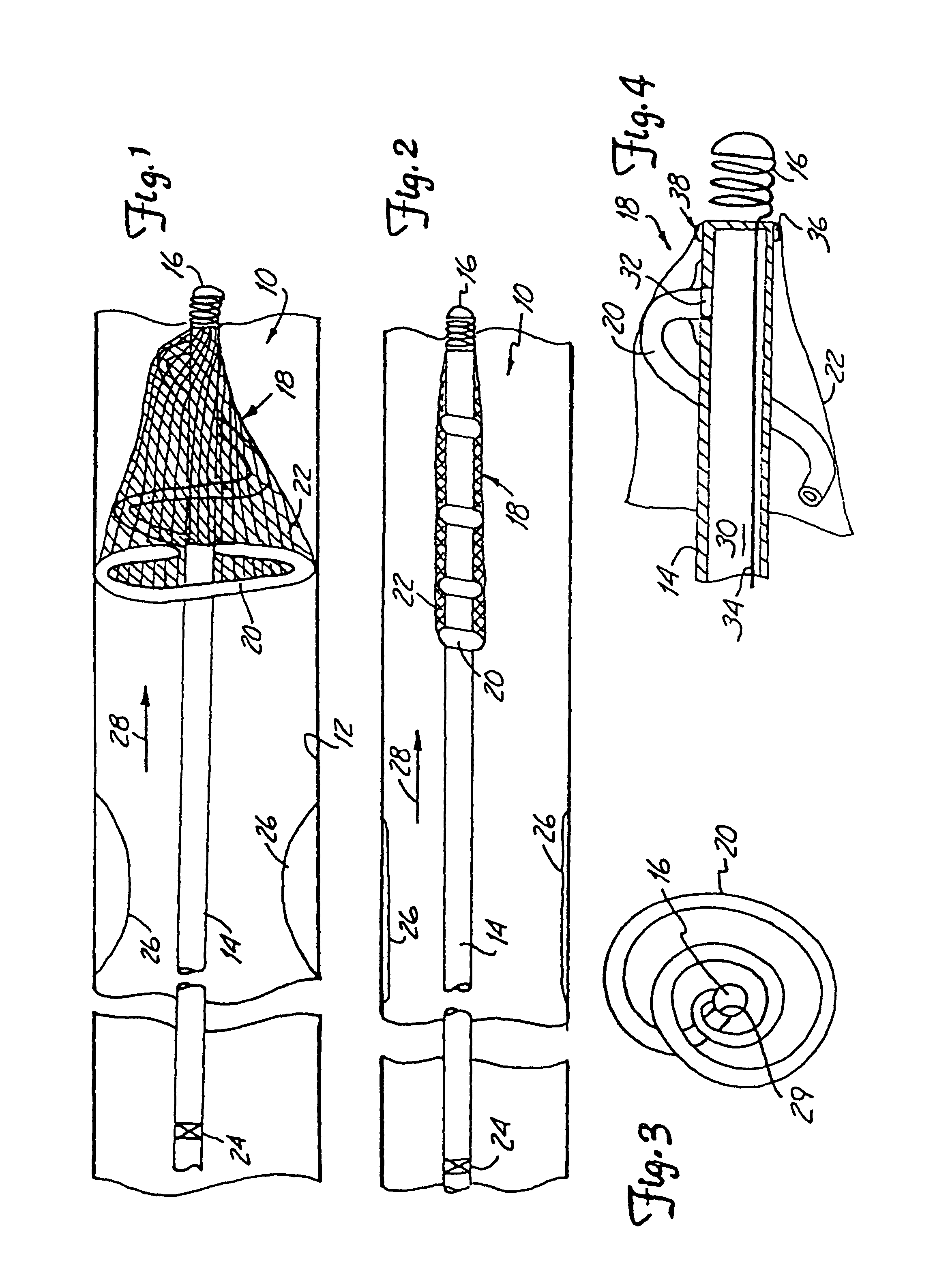
[0032]FIG. 1 illustrates protection device 10 in a deployed position within the lumen of a blood vessel 12. Protection device 10 preferably includes hollow guidewire 14 (or a hypotube having the same general dimensions as a guidewire) having a coil tip 16, and a capturing assembly 18. Capturing assembly 18, in the embodiment shown in FIG. 1, includes an inflatable and expandable member 20 and mesh 22.

[0033]An interior of expandable member 20 is preferably coupled for fluid communication with an inner lumen of guidewire 14 at a distal region of guidewire 14. When deployed, inflatable member. 20 inflates and expands to the position shown in FIG. 1 such that capturing assembly 18 has an outer periphery which approximates the inner periphery of lumen 12.

[0034]Mesh 22 is preferably formed of woven or braided fibers or wires, or a microporous membrane, or other suitable filtering or netting-type material. In one preferred embodiment, mesh 22 is a microporous membrane having holes therein ...


PUM


Abstract

An emboli capturing system captures emboli in a body lumen. A first elongate member has a proximal end and a distal end. An expandable emboli capturing device is mounted proximate the distal end of the first elongate member, and is movable between a radially expanded position and a radially contracted position. When in the expanded position, the emboli capturing device forms a basket with a proximally opening mouth. A second elongate member has a proximal and a distal end with a lumen extending therebetween. The lumen is sized to slidably receive a portion of the first elongate member. An expandable delivery device is mounted to the distal end of the second elongate member and is movable from a radially retracted position to a radially expanded position. The delivery device has a receiving end configured to receive the emboli capturing device, and retains at least the mouth of the emboli capturing device in a radially retracted position.

Description

[0001]This application is a continuation application of U.S. application Ser. No. 10 / 650,304 filed Aug. 28, 2003 now abandoned, which is a continuation application of U.S. application Ser. No. 10 / 160,450 filed May 30, 2002, now U.S. Pat. No. 6,663,652, which is a continuation application of U.S. application Ser. No. 09 / 735,332 filed Dec. 12, 2000 now abandoned, which is a continuation application of U.S. application Ser. No. 09 / 409,497 filed Sep. 30, 1999, now U.S. Pat. No. 6,245,089, which is a continuation application of U.S. application Ser. No. 08 / 943,358 filed Oct. 3, 1997, now U.S. Pat. No. 6,001,118, which is a continuation-in-part of U.S. application Ser. No. 08 / 810,825 filed Mar. 6, 1997, now U.S. Pat. No. 5,814,064, which is a continuation-in-part of U.S. application Ser. No. 08 / 813,794 filed Mar. 6, 1997, now U.S. Pat. No. 5,827,324.[0002]The following co-pending patent application is hereby incorporated by reference U.S. patent application Ser. No. 08 / 813,794, entitled D...

Claims


Application Information

Patent Timeline
Patent Type & Authority Patents(United States)
IPC IPC(8): A61M29/00A61B17/00A61B17/22A61F2/00A61F2/01
CPCA61B17/221A61F2/013A61B2017/00539A61B2017/22049A61B2017/22061A61B2017/2212A61F2002/30092A61F2210/0014A61F2002/018A61F2230/0006A61F2230/0008A61F2230/0067A61F2230/0076A61F2230/008A61F2230/0086
Inventor DANIEL, JOHN M. K.BROOME, THOMAS E.HOLTAN, DAVID J.CASSELL, ROBERT L.ADAMS, DANIEL O.
Owner BOSTON SCI SCIMED INC
Why Eureka
Try Eureka