Collapsible hurdle with quick reset

a technology of quick reset and collapsible hurdles, applied in the field of collapsible hurdles, can solve the problems of not typically giving way or breaking, children's anxiety, and the risk of students still present, so as to reduce the user's fear of injury, and minimize the risk of injury

Inactive Publication Date: 2010-08-31
MOORE THOMAS M
View PDF7 Cites 19 Cited by
  • Summary
  • Abstract
  • Description
  • Claims
  • Application Information

AI Technical Summary

Benefits of technology

[0007]Another aspect of this invention relates to a hurdle which comprises a substantially horizontal crossbar supported by a pair of laterally spaced legs. At least one component from a group of components comprising the crossbar and legs separates into separate sections when the crossbar is struck by a user who is attempting to clear the crossbar to permit the hurdle to give way or collapse to minimize the risk of injury to the user. A flexible member keeps the separate sections at least loosely joined together after the hurdle has given way or collapsed to prevent the user from having to collect completely disconnected sections from the ground to reset the hurdle.
[0008]Yet another aspect of this invention relates to a hurdle which comprises a crossbar and a pair of vertical legs that are designed to at least partially give way or collapse downwardly when the crossbar is struck by a user to minimize the risk of injury and thereby decrease the user's fear of injury. Either the crossbar is split into separate left and right sections or each of the legs is split into separate top and bottom sections. The separate sections of the crossbar or the legs break apart from an aligned, end-to-end orientation which they possess in an operative position of the hurdle into a nonaligned, end-to-end orientation after the hurdle has given way or collapsed downwardly. A member is provided for biasing the separate sections of the crossbar or the legs back into their aligned, end-to-end orientation when a user pulls the separate sections of the hurdle upwardly to reset the hurdle.

Problems solved by technology

However, some children are anxious when attempting to go over standard track hurdles.
This anxiety arises because of the inherent danger associated with any object, such as a hurdle, that has the potential to trip them up, causing them to fall.
Some light weight adjustable hurdles have been used to address this issue, but the risk is still there for some students.
However, known hurdles do not typically give way or break apart easily.
Since this is known to many users, trying to leap over the standard hurdles of the type known in the prior art is still an anxiety producing event due to the fear of injury.
When younger children or relatively unskilled runners are using hurdles, it is common for them to frequently strike and knock a hurdle over.
This means that someone, often a coach or teacher, must frequently reset or reassemble the hurdle.
If this is an onerous or time consuming task, such as might happen if the hurdle splits into separate, disparate parts that must be individually picked up off the ground and put back together, then the time required for the task is a disincentive to the use of such a hurdle.

Method used


Image

  • Collapsible hurdle with quick reset
  • Collapsible hurdle with quick reset
  • Collapsible hurdle with quick reset

Examples


first embodiment

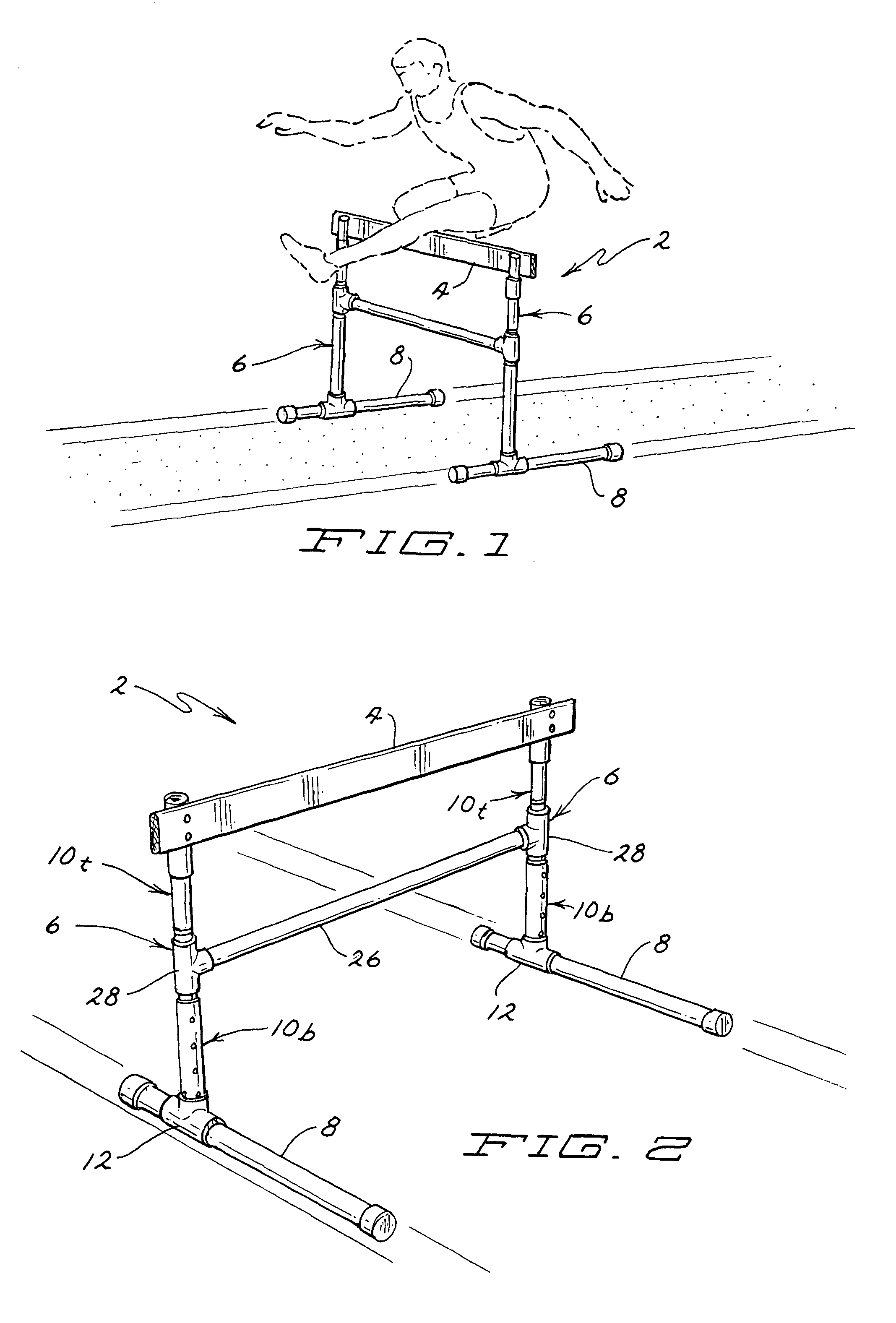
[0019]a hurdle according to this invention is illustrated generally as 2 in FIG. 1. Hurdle 2 comprises a substantially horizontal, laterally extending crossbar 4 supported above the ground by a pair of vertically extending uprights or legs 6. Legs 6 are laterally spaced apart with each leg 6 supporting one end of crossbar 4. The lower ends of legs 6 have horizontal ground engaging feet 8 that support hurdle 2 in an upright operative position as shown in FIG. 1.

[0020]When hurdle 2 is in the operative position shown in FIGS. 1 and 2, feet 8 at the lower ends of legs 6 extend perpendicularly to crossbar 4 for a short distance to either side of crossbar 4 so that hurdle 2 is self supporting. When hurdle 2 is in the operative position, legs 6 also extend vertically straight upwardly and downwardly. Crossbar 4 is located at the top of legs 6 in a substantially horizontal orientation. Crossbar 4 is approximately 40″ wide though this can be lengthened or shortened as desired. A user can att...

second embodiment

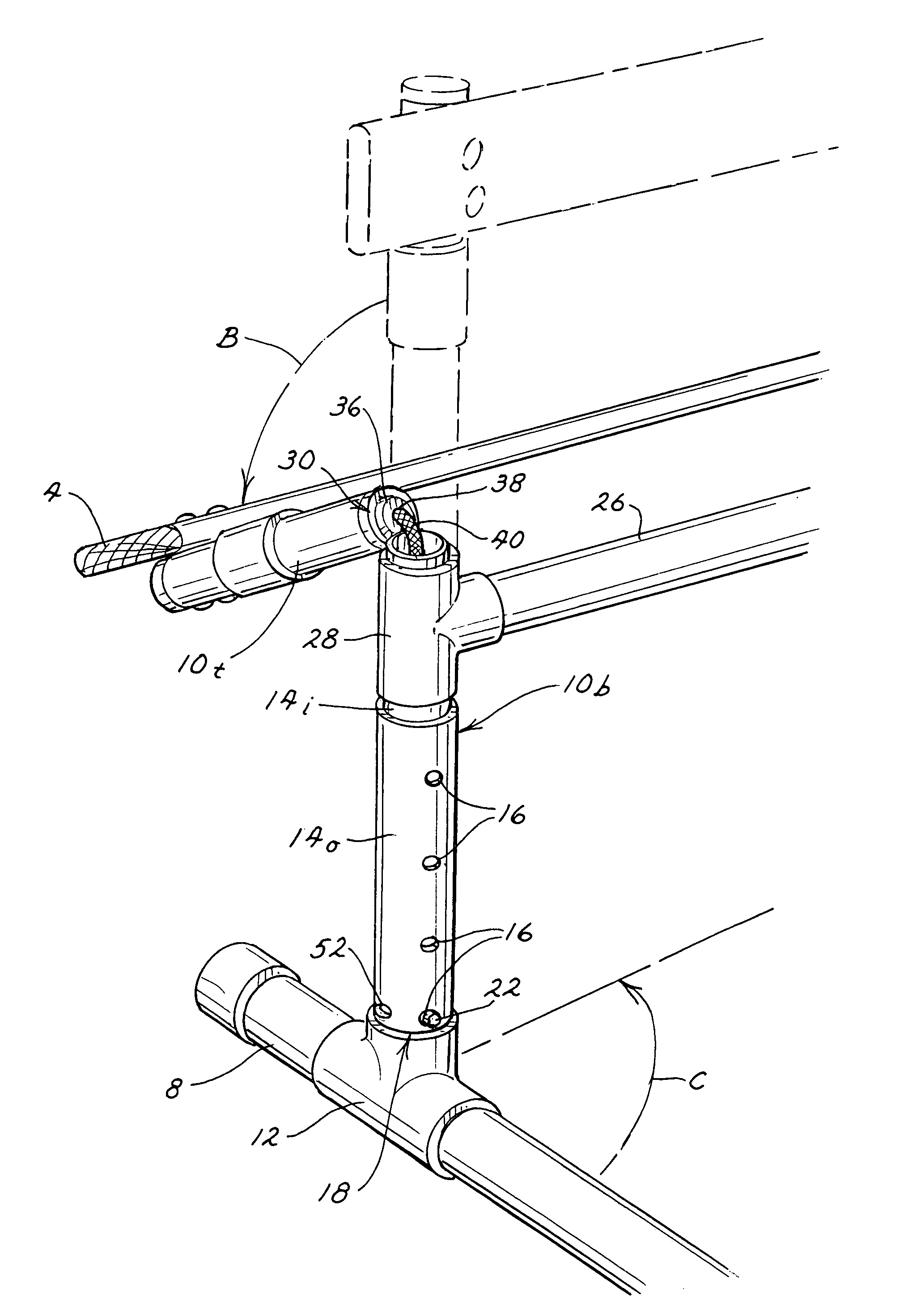
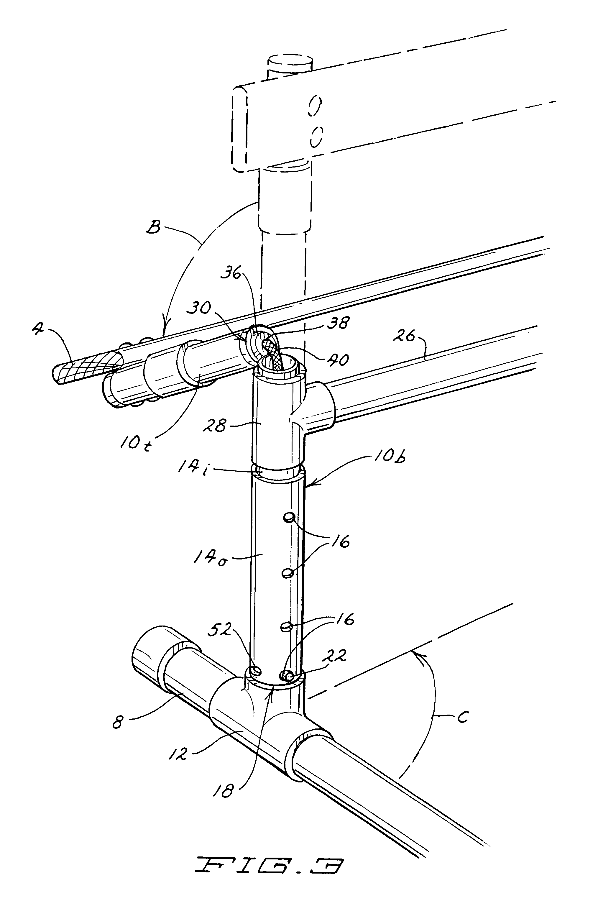
[0023]Inner portion 14i carries a spring lock 18 inside the hollow interior of inner portion 14i. Spring lock 18 used inside inner portion 14i is not completely shown in FIGS. 1-5, but is shown in conjunction with the hurdle of this invention depicted in FIGS. 6-9. Accordingly, reference will now be had to FIG. 9 to illustrate and describe spring lock 18 since spring lock 18 depicted in FIG. 9 is the same as spring lock 18 used inside inner portion 14i.

[0024]Referring now to FIG. 9, spring lock 18 has a simple U or V-shape provided by a pair of spaced legs 20. An outwardly protruding locking tab 22 is carried at the free end of one leg 20. As can be seen in FIG. 9, legs 20 of spring lock 18 can be partially squeezed or compressed together to allow spring lock 18 to be inserted into the interior of a hollow cylindrical member, such as inner portion 14i. Following such insertion, legs 20 of spring lock 18, and locking tab 22 carried on one leg 22, are biased radially outwardly as leg...


PUM


Abstract

A hurdle has a crossbar and a pair of vertical legs. The hurdle is designed to give way or collapse when the crossbar is struck by a user to minimize the risk of injury and thereby decrease the user's fear of injury. This is done either by splitting the crossbar into separate left and right sections, or by splitting each of the legs into separate top and bottom sections. This permits the separate sections to break apart from an aligned, end-to-end orientation which they possess in an operative position of the hurdle into a nonaligned orientation after the hurdle has given way or collapsed. An elastic member connects the separate sections and urges the sections back into their aligned, end-to-end orientation when a user picks the sections of the hurdle up and resets the hurdle.

Description

CROSS REFERENCE TO RELATED APPLICATIONS[0001]This application claims the benefit of one or more previously filed copending provisional applications identified as follows: Application Ser. No. 60 / 900,057 filed Feb. 7, 2007.TECHNICAL FIELD[0002]This invention relates to a hurdle that a person runs or jumps over during various athletic activities, such as track events known as the high or low hurdles. More particularly, this invention relates to a hurdle that gives way or collapses easily when it is struck or fallen on by a person attempting to clear the hurdle but that can also be quickly and easily reset.BACKGROUND OF THE INVENTION[0003]Track and field is a part of the physical education programs of many high schools, junior high schools and elementary schools. Most children seem to enjoy all the track events, including hurdle training and races. However, some children are anxious when attempting to go over standard track hurdles. This anxiety arises because of the inherent danger as...

Claims


Application Information

Patent Timeline
Patent Type & Authority Patents(United States)
IPC IPC(8): A63B5/16
CPCA63K3/043
Inventor MOORE, THOMAS M.
Owner MOORE THOMAS M
Why Eureka
Try Eureka