Variable stride exercise device
- Summary
- Abstract
- Description
- Claims
- Application Information
AI Technical Summary
Benefits of technology
Problems solved by technology
Method used
Image
Examples
first embodiment
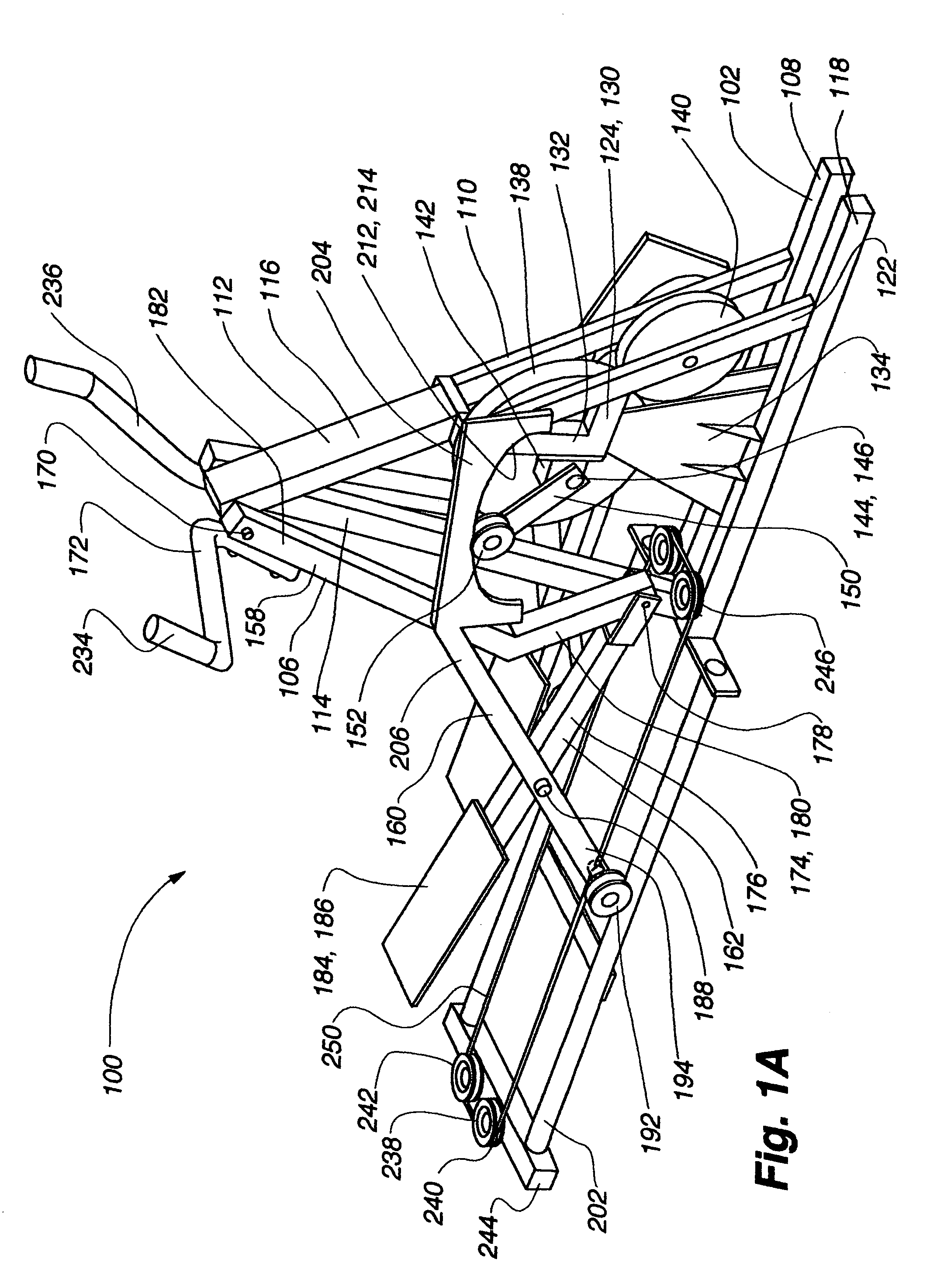
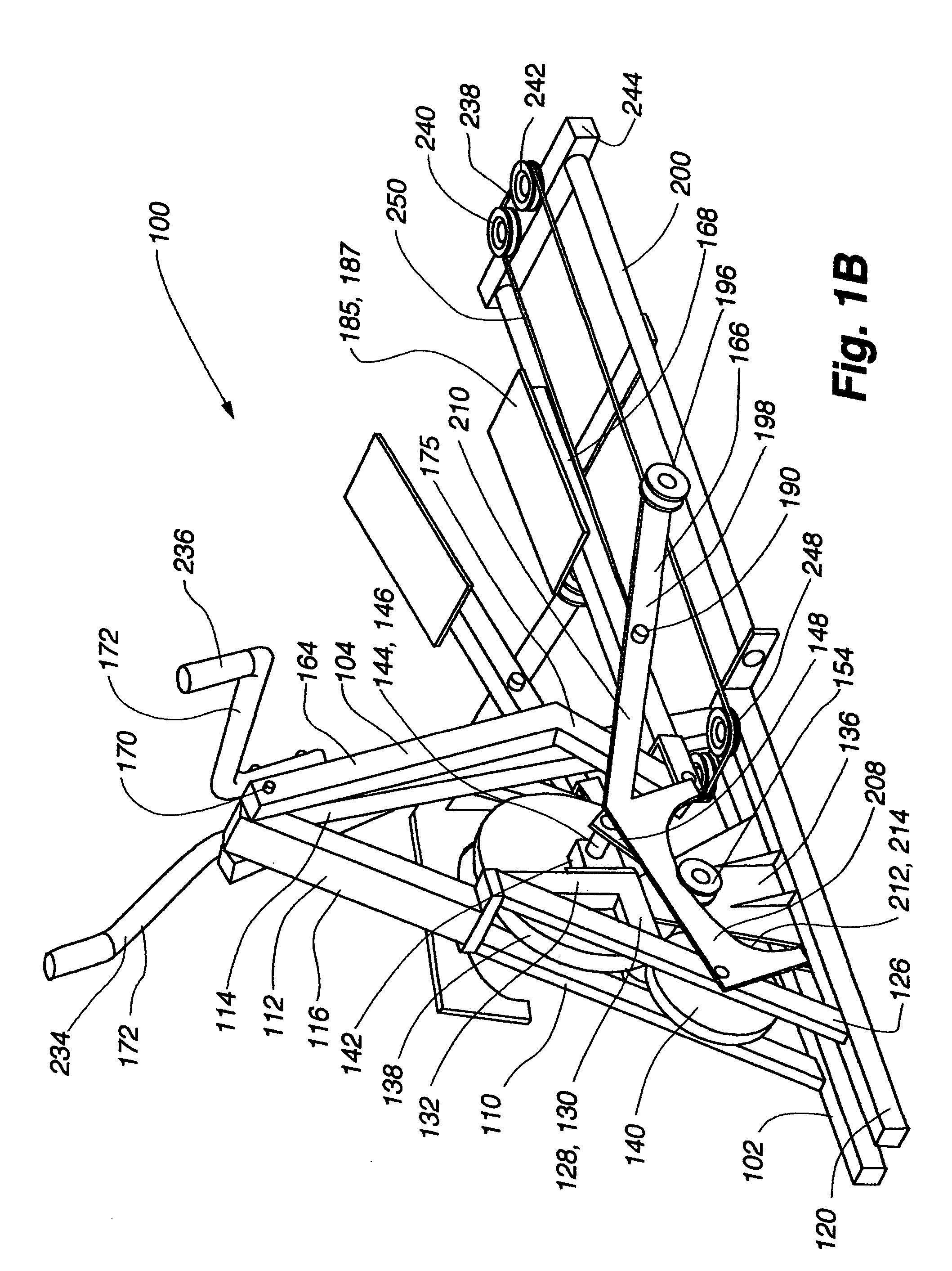
[0086]an exercise device 100 conforming to aspects of the present invention is shown in FIGS. 1A-2. The exercise device 100 includes a frame 102 having a left linkage assembly 104 and a right linkage assembly 106 connected therewith. The left linkage assembly 104 is substantially a mirror image of the right linkage assembly. The frame includes a base portion 108, a fork assembly 110, a front post 112, and a rear post 114. The combination of the fork assembly, the front post, and the rear post pivotally supports the linkage assemblies as well as supports the components that variably support the linkage assemblies.
[0087]The fork assembly 110, the front post 112, and the rear post 114 define an A-frame like support structure 116. More particularly, the fork assembly 110 and the rear post 114 are connected with the base portion 108. At the front of the device, the fork assembly 110 extends upwardly and rearwardly from the base portion 108. The front post 112 extends upwardly from the fo...
embodiment 266
[0129]A second alternative embodiment 266 of an interconnection assembly is illustrated in FIG. 9 and includes a teeter member 268, a right interconnection link 270, a left interconnection link 272, a right U-bracket 274, and a left U-bracket 276. A teeter axle 278 extends forwardly from the front post 112 and is adapted to pivotally support the teeter member 268. The left interconnection link 272 is pivotally connected with a left portion 280 of the teeter member 268 and extends downwardly therefrom to pivotally connect with the left U-bracket 276, which is rigidly connected with the left swing link 164 near the upper pivot 170. The right interconnecting link 272 is pivotally connected with a right portion 282 of the teeter member 268 and extends downwardly therefrom to pivotally connect with the right U-bracket 274, which is rigidly connected with the right swing link 158 near the upper pivot 170. When either of the swing links swing rearward, the associated U-bracket pivots downw...
second embodiment
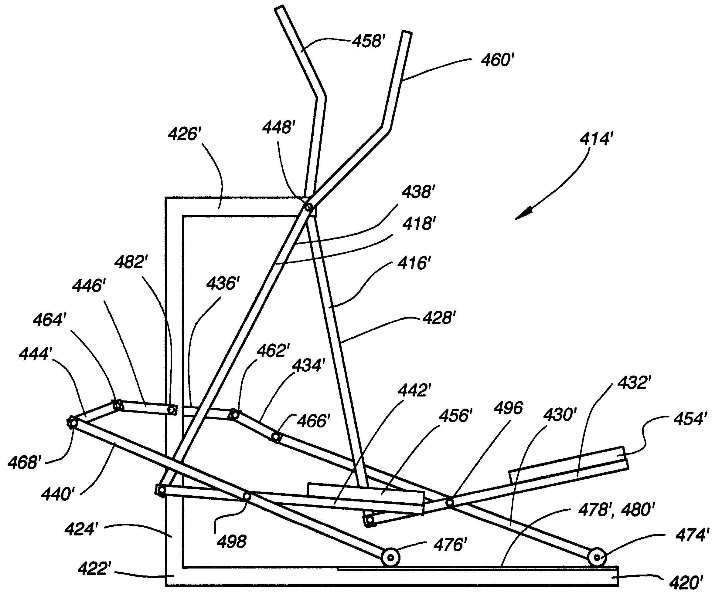
[0150]the exercise device 100′ shown in FIG. 10 also includes an interconnection assembly 266′ that acts to move the linkage assemblies in opposite directions. A detailed view of the interconnection assembly 266′ is shown in FIG. 15 and is structurally similar to the interconnection described above with reference to FIG. 9, except the teeter member is located below the upper pivot 170′. As such, the interconnection assembly 266′ includes a teeter member 268′, a right interconnection link 270′, a left interconnection link 272′, a right U-bracket 274′, and a left U-bracket 276′. A teeter axle 278′ extends forwardly from the front post 294 and is adapted to pivotally support the teeter member. The left interconnection link 272′ is pivotally connected with the left portion 280′ of the teeter member 268′ and extends upwardly therefrom to pivotally connect with the left U-bracket 276′, which is rigidly connected with the left swing link 164′ near the upper pivot 170′. The right interconne...
PUM
 Abstract
Description
Claims
Application Information
 - R&D
- Intellectual Property
- Life Sciences
- Materials
- Tech Scout
- Unparalleled Data Quality
- Higher Quality Content
- 60% Fewer Hallucinations
Browse by: Latest US Patents, China's latest patents, Technical Efficacy Thesaurus, Application Domain, Technology Topic, Popular Technical Reports.
© 2025 PatSnap. All rights reserved.Legal|Privacy policy|Modern Slavery Act Transparency Statement|Sitemap|About US| Contact US: help@patsnap.com


