Oscillating motor for a personal care appliance

a technology for personal care appliances and oscillating motors, which is applied in the direction of cleaning equipment, manufacturing tools, carpet cleaners, etc., can solve the problems of manufacturing difficulties and other elements that add significant expense to the manufacture of appliances

Active Publication Date: 2010-08-31
LOREAL SA
View PDF14 Cites 126 Cited by
  • Summary
  • Abstract
  • Description
  • Claims
  • Application Information

AI Technical Summary

Problems solved by technology

Such bearings or other elements typically add significant expense and manufacturing difficulties to the manufacture of the appliance as well as reliability / durability concerns to the use of the appliance.

Method used


Image

  • Oscillating motor for a personal care appliance
  • Oscillating motor for a personal care appliance
  • Oscillating motor for a personal care appliance

Examples


Embodiment Construction

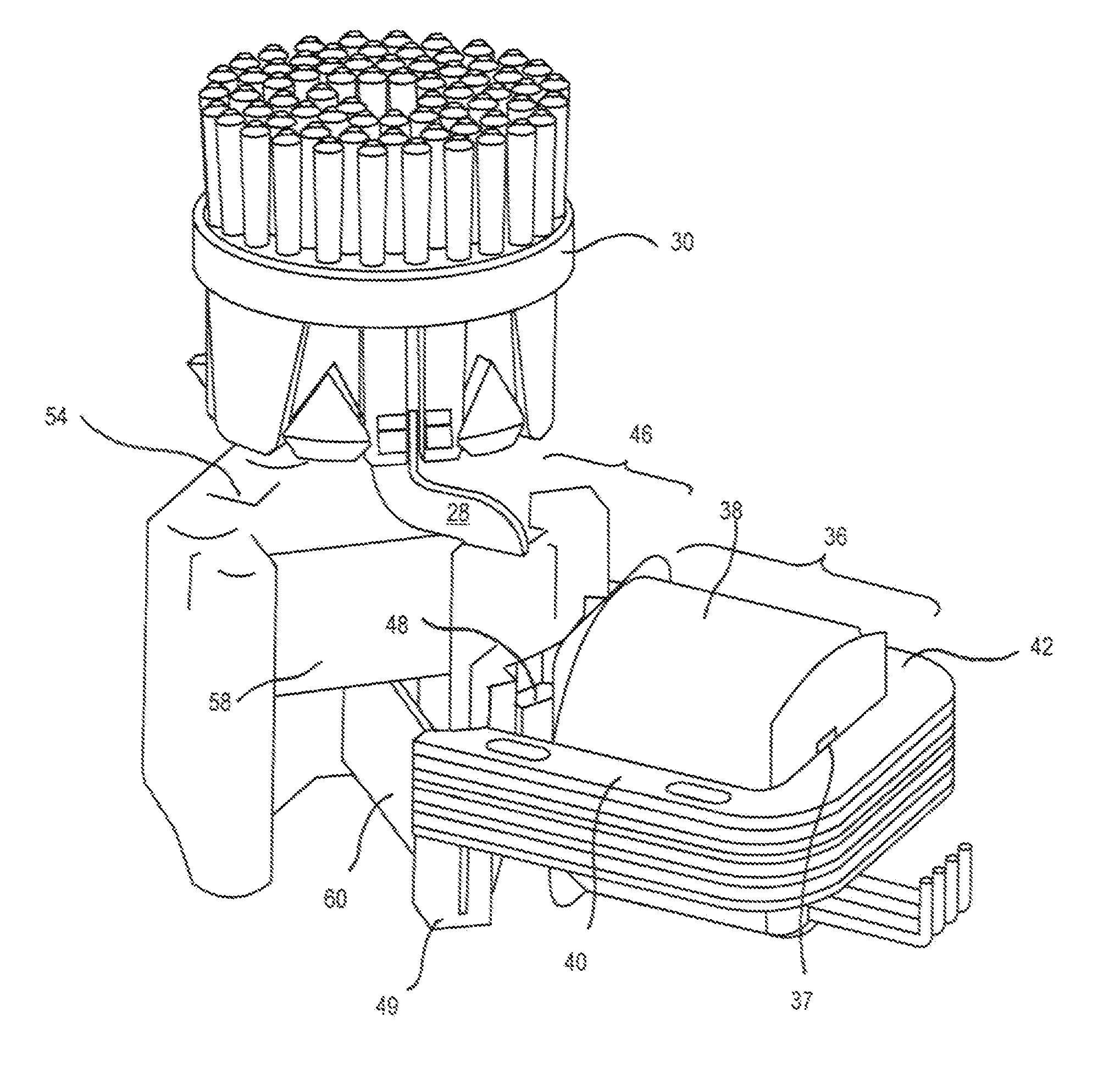
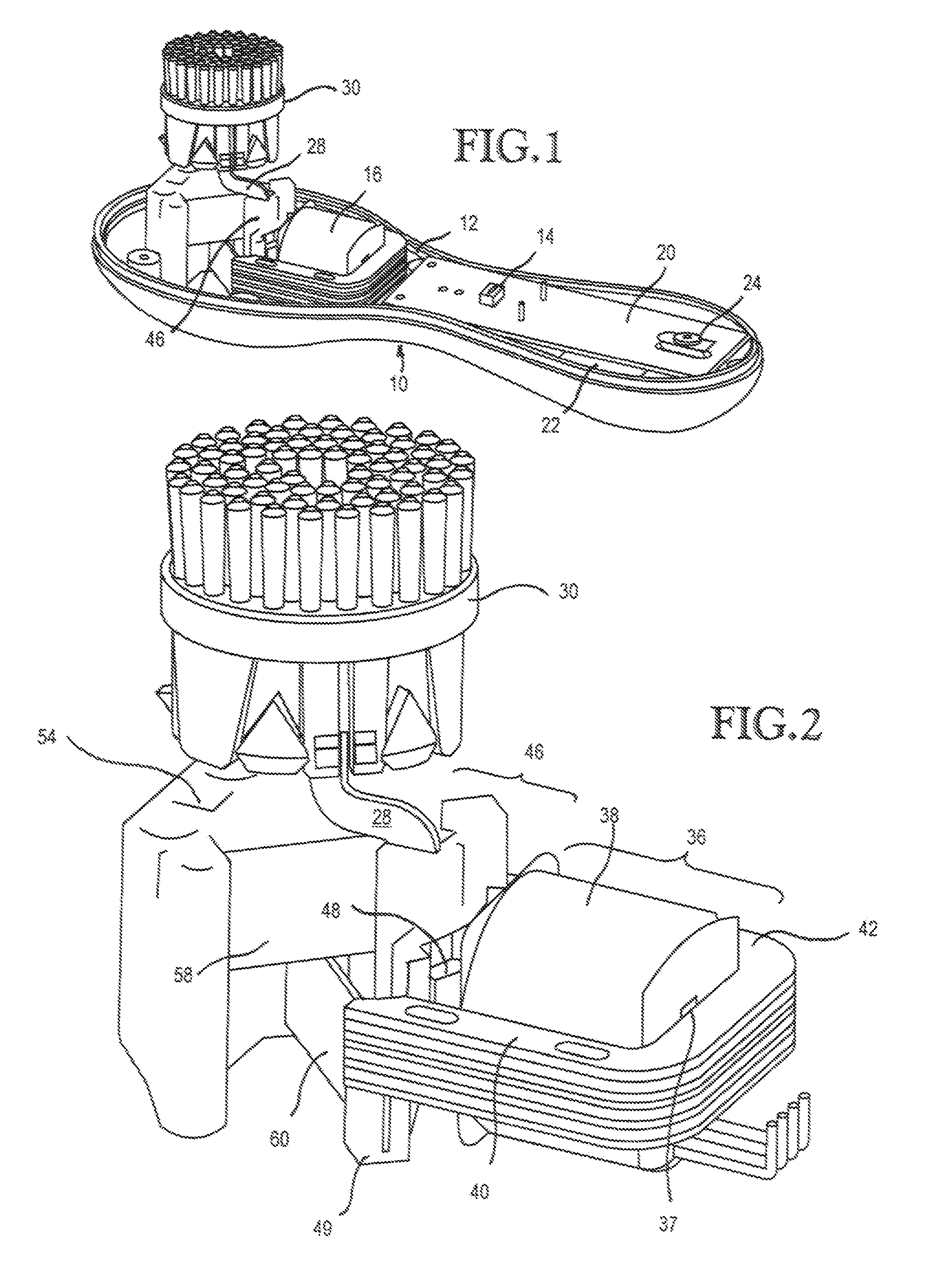
[0011]FIG. 1 shows a personal care appliance in the form of a power skin brush. The personal care appliance 10 includes a case or housing 12 through which an on / off switch 14 extends to contact a button on the case or the like for control of the appliance. Positioned within case 12 is a motor 16 and a drive assembly, which includes an electronic drive circuit 20 and rechargeable batteries 22 which provide a self-contained source of power for the appliance. The appliance 10 in the embodiment shown also includes a charging coil 24 which operates with a conventional charger (not shown) to maintain batteries 22 in a charged condition.

[0012]The appliance further includes a workpiece mounting arm 28 which extends from an armature portion of the motor 16. Mounted on the free end of arm 28 is a specific workpiece 30, which in the embodiment shown is a skin brush. Such a skin brush is shown and described in more detail in co-pending application Ser. No. 10 / 873,352, which is owned by the assi...


PUM


Abstract

The motor includes an E-core stator assembly with a source of alternating current and an armature portion mounted to be responsive to the stator to oscillate back and forth through an arc portion of the personal care appliance and flexure elements are connected between the armature and the mounting member, the flexure elements crossing each other, wherein the crossing point defines a pivot point about which the armature rotates. A workpiece assembly, which includes a mounting arm, is configured so that a skin brush mounted on a free end of the mounting arm has an axis of rotation about the pivot point.

Description

TECHNICAL FIELD[0001]This invention relates generally to motors for a personal care appliance, such as a power skin brush, and more specifically concerns an electromagnetic motor using flexure elements to produce an oscillating action of the workpiece portion of the personal care appliance.BACKGROUND OF THE INVENTION[0002]Personal care appliances typically use an internal motor to produce a particular workpiece movement / action, which in turn produces desired functional results. Examples of such appliances include power skin brushes, power toothbrushes and shavers, among others.[0003]Many such devices have a motor arrangement which produces an oscillating (back and forth) action rather than a purely rotational movement. Such arrangements require not only the typical motor bearing structures for support of the motion, but also specific structural elements to constrain the movement of the motor drive shaft and the workpiece to a selected angle / movement. Such bearings or other elements ...

Claims


Application Information

Patent Timeline
Patent Type & Authority Patents(United States)
IPC IPC(8): H02K33/00
CPCH02K33/16A46B13/008A46B13/02A46B2200/1006A46B2200/102A46B2200/1066A61C17/00H02K33/00H02K33/18
Inventor REISHUS, RICHARD A.MEGINNISS, II, STEPHEN M.PILCHER, KENNETH A.
Owner LOREAL SA
Why Eureka
Try Eureka