
Gas pressure regulator

a technology of gas pressure regulator and silencing device, which is applied in the direction of fluid pressure control, process and machine control, instruments, etc., can solve the problems of inability to install, cannot be replaced, and the silencing device in the regulator that has already been installed has to be replaced, etc., to achieve the effect of simple and inexpensive assembly and practical maintenan

Active Publication Date: 2010-09-07
O M T OFFICINA MECCANICA TARTARINI SPA
View PDF15 Cites 14 Cited by
  • Summary
  • Abstract
  • Description
  • Claims
  • Application Information

AI Technical Summary

Benefits of technology

"The technical effect of this patent is to provide a pressure regulator that is simple, inexpensive, and easy to assemble and maintain. This aims to overcome the disadvantages of existing pressure regulators."

Problems solved by technology

The main disadvantage is that they cannot be installed unless the pressure regulator is totally disassembled.
That means that once a certain type of silencing device has been installed, it cannot be substituted without completely disassembling the regulator.
In many cases, however, the silencing device in a regulator that has already been installed has to be replaced because it exceeds permitted noise levels or because it has to be adapted to different flow conditions.
In these situations, changing the silencing devices in prior art pressure regulators involves considerable assembly difficulties.

Method used


Image

  • Gas pressure regulator
  • Gas pressure regulator
  • Gas pressure regulator

Examples


Embodiment Construction

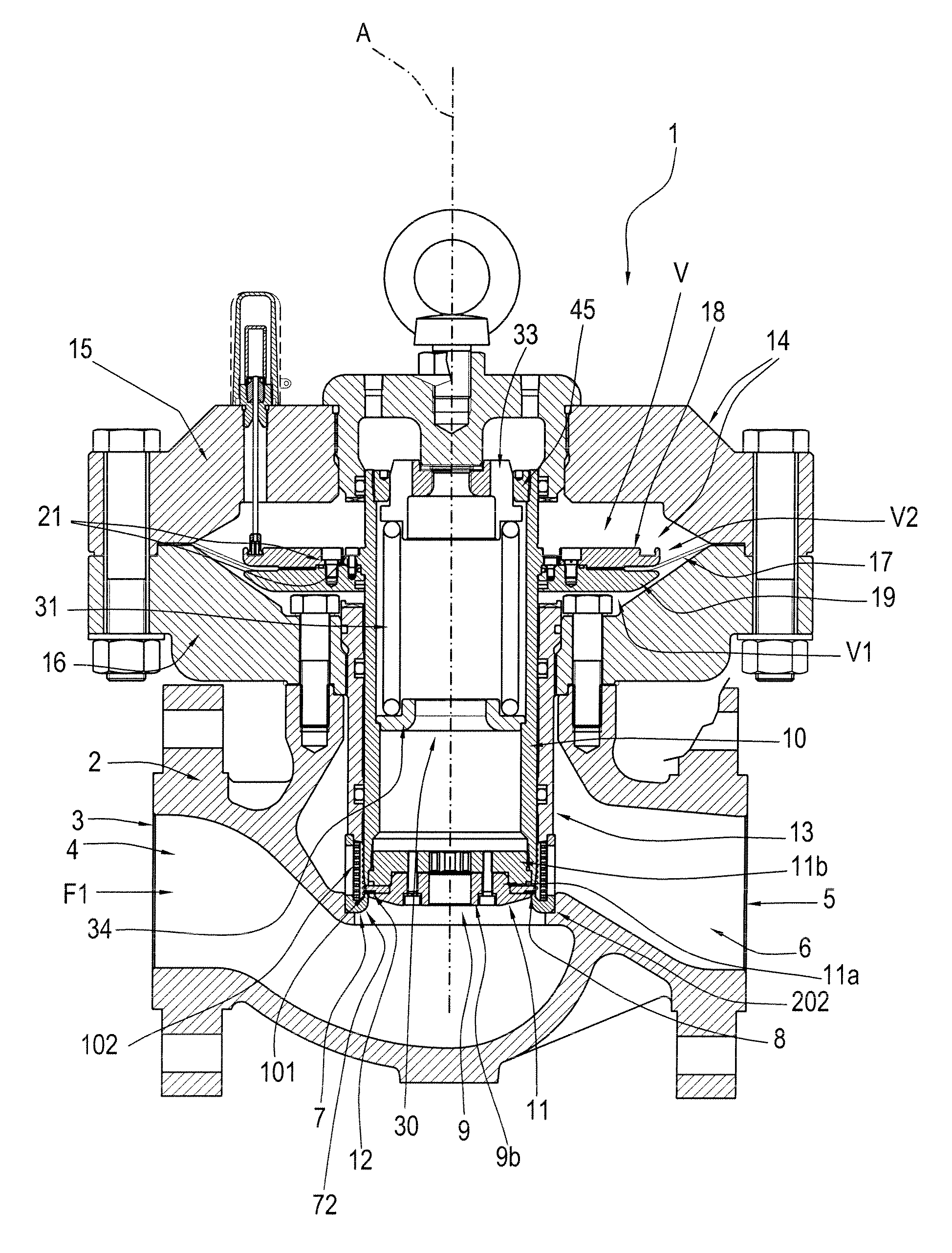
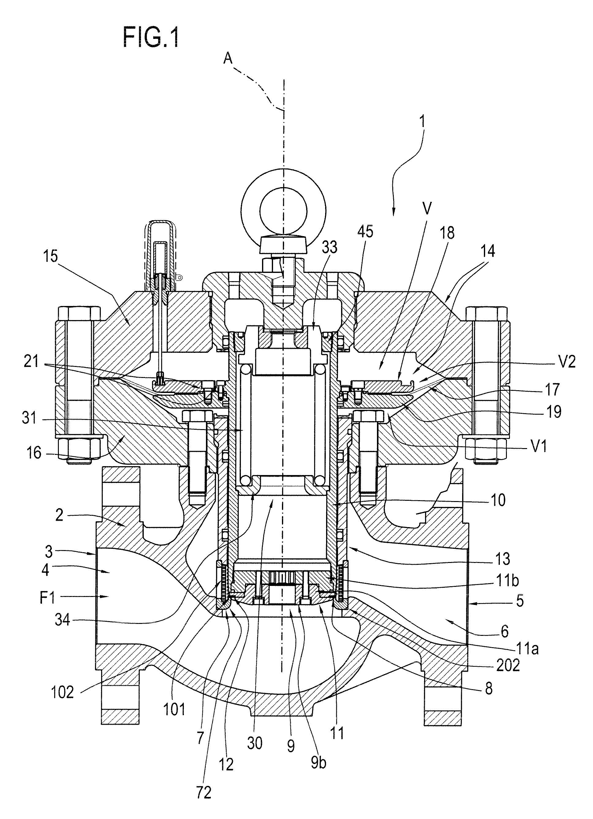
[0032]With reference to FIG. 1, the numeral 1 denotes in its entirety a gas pressure regulator made in accordance with this invention.

[0033]The pressure regulator 1 comprises a main body 2 with an inlet opening 3 through which the gas enters at a first delivery pressure, said inlet opening 3 being connected to a respective first inlet pipe 4, and a gas outlet opening 5 connected to a respective second outlet pipe 6 in which the gas flows at a pressure that is different from the delivery pressure.

[0034]The second outlet pipe 6 is located downstream of the first inlet pipe 4 relative to the direction, indicated by the arrow F1, in which the gas flows through the regulator 1.

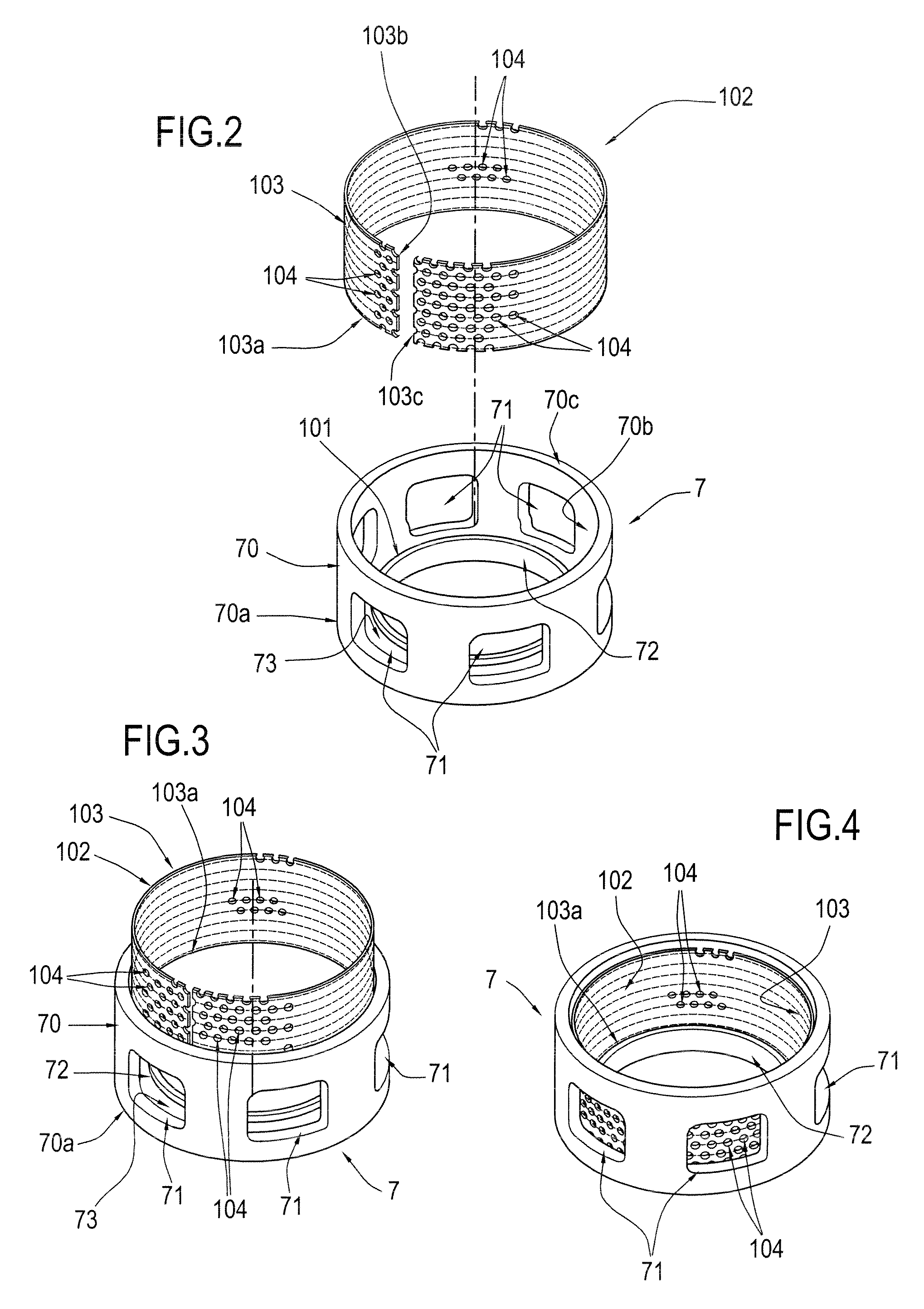
[0035]Between the first pipe 4 and the second pipe 6 there is an axially symmetric body 7, which will be described in detail below, said body 7 defining a calibrated gas passage 8.

[0036]The regulator 1 also comprises, inside it, a shutter 9 that moves lengthways along a first defined line D to adjust the opening of...


PUM


Abstract

The gas pressure regulator (1) comprises a main body (2) having a first, gas inlet pipe (4) and a second, gas outlet pipe (6), a calibrated gas passage (8) through which the gas flows from the first pipe (4) to the second pipe (6), a shutter (9) housed at least partially in the main body (2) and a silencing element (102) also housed in the body (2).

Description

RELATED APPLICATIONS[0001]This application claims priority to Italian application number BO2006 A0004000 dated May 24, 2006.TECHNICAL FIELD[0002]This invention relates to a gas pressure regulator.[0003]In particular, the invention relates to a pressure regulator fitted with a noise reducing device.[0004]Pressure regulators currently used are also commonly known as “pressure reducers” because their regulating action is achieved by reducing the gas delivery pressure through laminar flow elements.[0005]Regulators known in prior art basically comprise a main body with an inlet through which gas flows in at high pressure and an outlet through which the gas flows out at reduced pressure. This main body houses means for controlling and regulating the gas flow.[0006]The controlling and regulating means comprise at least one shutter, actuated by spring and diaphragm systems which enable the shutter to slide on its shaft, and a pilot device which measures the pressure of the gas upstream and ...

Claims


Application Information

Patent Timeline
Patent Type & Authority Patents(United States)
IPC IPC(8): F16K47/02
CPCF16K47/08F16K1/427G05D16/0658Y10T137/86759Y10T137/86807
Inventor ZECCHI, STEFANOMONTI, ANDREA
Owner O M T OFFICINA MECCANICA TARTARINI SPA
Learn More