
Equipment with a pivoting handle, in particular to be suspended in an aircraft console

a technology of aircraft console and equipment, which is applied in the direction of handbags, manufacturing tools, transportation and packaging, etc., can solve the problems of handle jamming and hand jamming, and achieve the effect of facilitating the actual extraction of equipment, simple and inexpensive assembly and manufacturing

Inactive Publication Date: 2006-09-19
THALES SA
View PDF13 Cites 1 Cited by
  • Summary
  • Abstract
  • Description
  • Claims
  • Application Information

AI Technical Summary

Benefits of technology

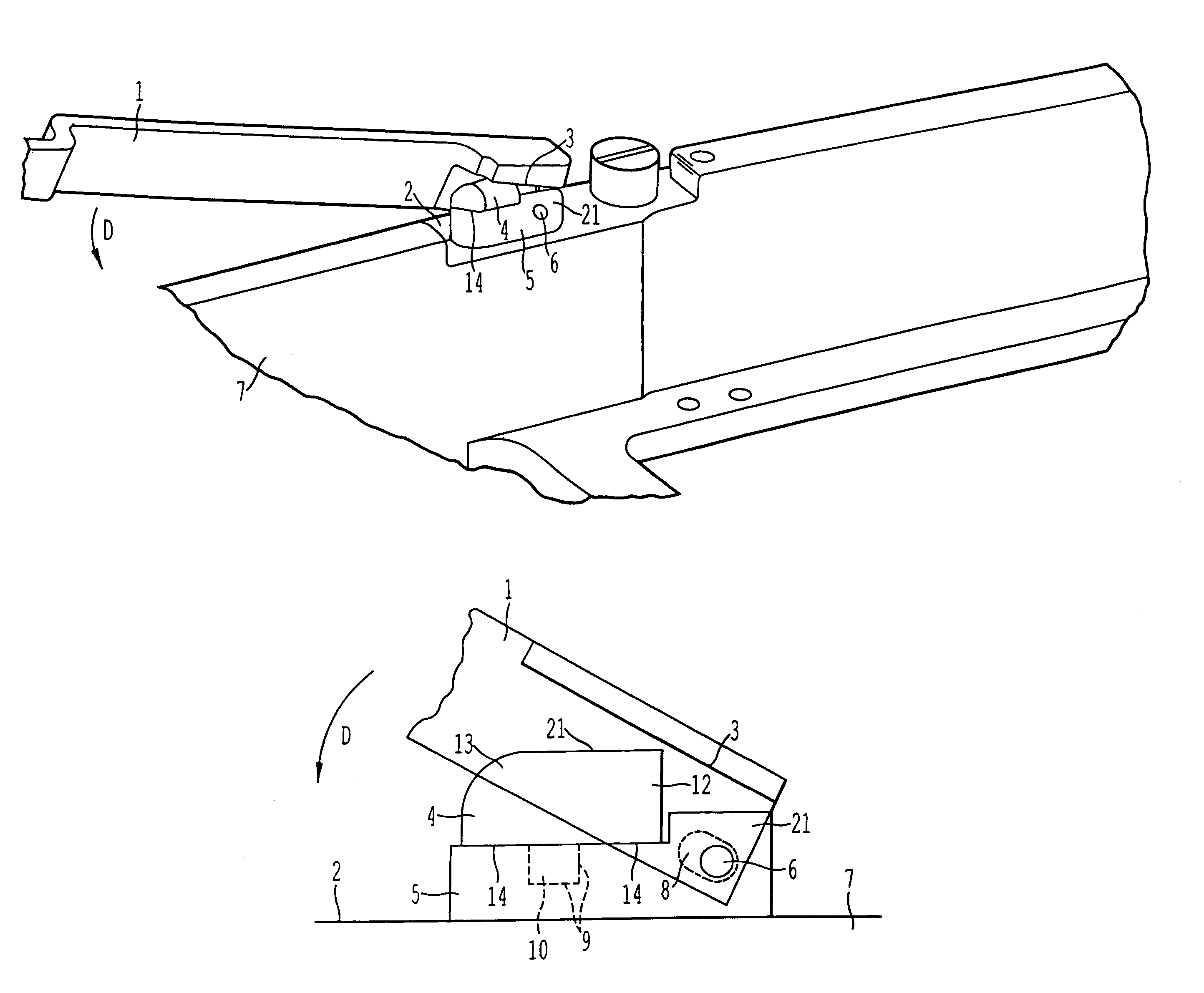
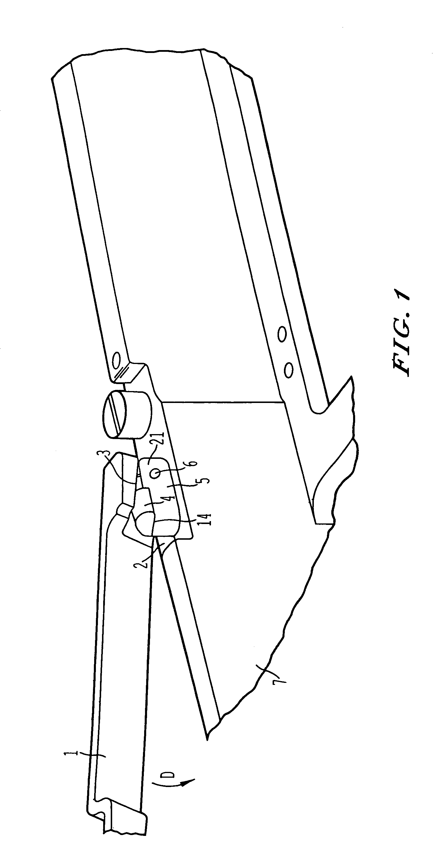
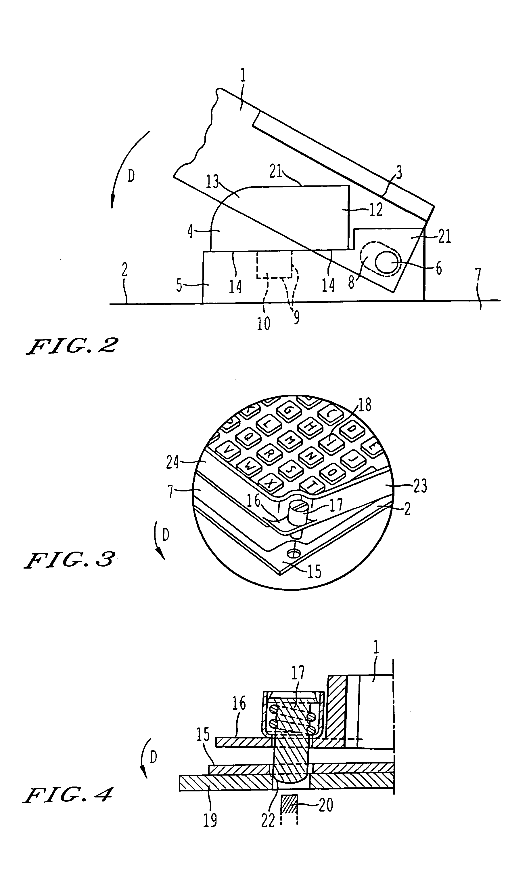
[0004]The invention proposes an equipment structured so that the handle is automatically rendered accessible when the equipment is to be extracted. For that, the handle is made accessible by automatic ejection, after unlocking, for example, of the equipment and of the associated pivoting handle, thus facilitating the actual extraction of the equipment. The means allowing this automatic ejection of the handle are simple and inexpensive to assemble and to manufacture.

Problems solved by technology

When an operator wishes to extract this equipment from the system, particularly from a system with significant constraints on small size, he often finds the handle jammed, and extraction is then often performed with damage to the equipment and to any nearby equipment that might be present in the same system, by using tools of the lever type in order to access the handle.
There are many reasons why the handle might jam, for example a tight space constraint forcing various equipments to be fitted into one and the same system in the most compact way possible, or alternatively misalignment leading to the handle jamming as it is installed in the system.

Method used


Image

  • Equipment with a pivoting handle, in particular to be suspended in an aircraft console
  • Equipment with a pivoting handle, in particular to be suspended in an aircraft console
  • Equipment with a pivoting handle, in particular to be suspended in an aircraft console

Examples


Embodiment Construction

[0012]The equipment according to the invention comprises a support. A pivoting handle is assembled with the support by at least one pivot pin. The pivoting handle may rest on at least one surface of the support when the handle is folded back, making the equipment as a whole more compact. The handle may in fact rest on all or part of one or several surfaces of the support. The handle comprises at least one bearing surface. The equipment comprises at least one pad of elastic material which is situated between the bearing surface and the support so that when the handle is folded back after the equipment has been installed, that is to say when the handle is resting on the surface of the support, the pad of elastic material is compressed between the bearing surface and the support. In all the remainder of the text, unless mentioned otherwise, pad and pad of elastic material will be used interchangeably. Thus, upon extraction, after unlocking, the compressed pad tends to revert to its ini...


PUM


Abstract

An equipment with pivoting handles. The equipment includes a support and a pivoting handle that are assembled by at least one pivot pin, the pivoting handle being able to rest on at least one surface of the support. The handle includes at least one bearing surface and the equipment includes at least one pad of elastic material arranged to be compressed against the support by the bearing surface when the handle is resting on the surface of the support. The equipment may be applied for example to suspended equipment for aircraft consoles.

Description

CROSS-REFERENCE TO RELATED APPLICATIONS[0001]This application is a continuation of U.S. application Ser. No. 10 / 275,739, filed Nov. 8, 2002, and is based upon and claims the benefit of priority from PCT Application No. PCT / FR01 / 01249, filed Apr. 24, 2001, and the prior French Patent Application No. 00 05862, filed May 9, 2000, the entire contents of each are incorporated herein by reference.BACKGROUND OF THE INVENTION[0002]The invention relates to an equipment with a pivoting handle, and in particular to a suspended equipment for an aircraft console. The equipment has to be able to be fitted into a system and removed from this system, for example to be updated or replaced. In the preferred case of an aircraft console, the equipment installed on the console is advantageously mounted locked suspended via its front face on the console and has a pivoting handle to make it easier to install.[0003]Once the equipment has been installed in a system, the pivoting handle is folded back. When ...

Claims


Application Information

Patent Timeline
Patent Type & Authority Patents(United States)
IPC IPC(8): A45F5/00B60R11/00B60R11/02H05K7/14
CPCB60R11/02H05K7/1411B60R2011/0066Y10T16/513Y10T16/50B60R2011/0071Y10T292/57
Inventor LABROUSSE, GILLESTANTET, ALAIN
Owner THALES SA
Learn More