Electro-optical device and electronic apparatus

a technology applied in the field of optical devices and electronic devices, can solve the problems of difficult to read displayed information, limited light, and inability to obtain high-quality color images, and achieve the effects of easy reading, limited light, and easy reading

Active Publication Date: 2010-09-07
BOE TECH GRP CO LTD
View PDF15 Cites 0 Cited by
  • Summary
  • Abstract
  • Description
  • Claims
  • Application Information

AI Technical Summary

Benefits of technology

[0007]An advantage of the invention is that it provides an electro-optical device in which information displayed in a reflective mode can be easily read, and an electronic apparatus having the electro-optical device.
[0008]According to an aspect of the invention, there is provided an electro-optical device including pixels arranged in a matrix, each pixel having a plurality of color-display sub-pixels corresponding to a plurality of colors and a monochrome-display sub-pixel. The color-display sub-pixel and the monochrome-display sub-pixel can perform gray-scale display independently. One of the color-display sub-pixels and the monochrome-display sub-pixel displays an image in a transmissive mode in which light emitted from a light source is modulated, while the other type of sub-pixel displays an image in a reflective mode in which light incident from outside is modulated.
[0009]According to the invention, for example, it is possible to display color images in a transmissive mode by means of the color-display sub-pixels and to display monochrome images in a reflective mode by means of the monochrome-display sub-pixel. In this case, since external light is required to display images in the reflective mode, the amount of light is limited. However, since monochrome images are displayed in the reflective mode, the light will not transmit a color filter layer unlike a case in which color images are displayed. Thus, since light loss upon transmitting the color filter layer does not occur in the reflective mode, bright images can be displayed so that displayed information can be easily read. Also, color signals displayed in the monochrome mode are displayed in gray-scale which is difficult to be discriminated. However, according to the invention, different image signals can be supplied to the monochrome-display sub-pixel and the color-display sub-pixel. Accordingly, it is possible to display high-quality color images in the transmissive mode and to display high-quality monochrome images in the reflective mode.
[0010]In the electro-optical device according to the aspect of the invention, it is preferable that, in each pixel, different image signals be supplied to the color-display sub-pixels and the monochrome-display sub-pixel, respectively.
[0011]Further, in the electro-optical device according to the aspect of the invention, it is preferable that the color-display sub-pixel display an image in a transmissive mode and the monochrome-display sub-pixel display an image in a reflective mode.
[0012]In this case, it is preferable that an electro-optical material layer interposed between a pair of substrates to modulate light be further provided. Further, it is preferable that the electro-optical material layer be thicker in the color-display sub-pixels than in the monochrome-display sub-pixel. Light transmits the electro-optical material layer twice in the reflective mode, while light transmits the electro-optical material layer once in the transmissive mode. However, by making the electro-optical material layer in the color-display sub-pixel thicker, it is possible to optimize retardation both in the color-display sub-pixel and in the monochrome-display sub-pixel.

Problems solved by technology

However, a transflective electro-optical device disclosed in Japanese Unexamined Patent Application Publication No. 2004-77544, in which external light is required to display color images in a reflective mode, has a problem in that the amount of light is limited.
As a result, high-quality color images cannot be obtained, and thus it is difficult to read displayed information.
In this case, since external light is required to display images in the reflective mode, the amount of light is limited.
However, since monochrome images are displayed in the reflective mode, the light will not transmit a color filter layer unlike a case in which color images are displayed.
Also, color signals displayed in the monochrome mode are displayed in gray-scale which is difficult to be discriminated.

Method used


Image

  • Electro-optical device and electronic apparatus
  • Electro-optical device and electronic apparatus
  • Electro-optical device and electronic apparatus

Examples


first embodiment

Overall Configuration of Electro-Optical Device

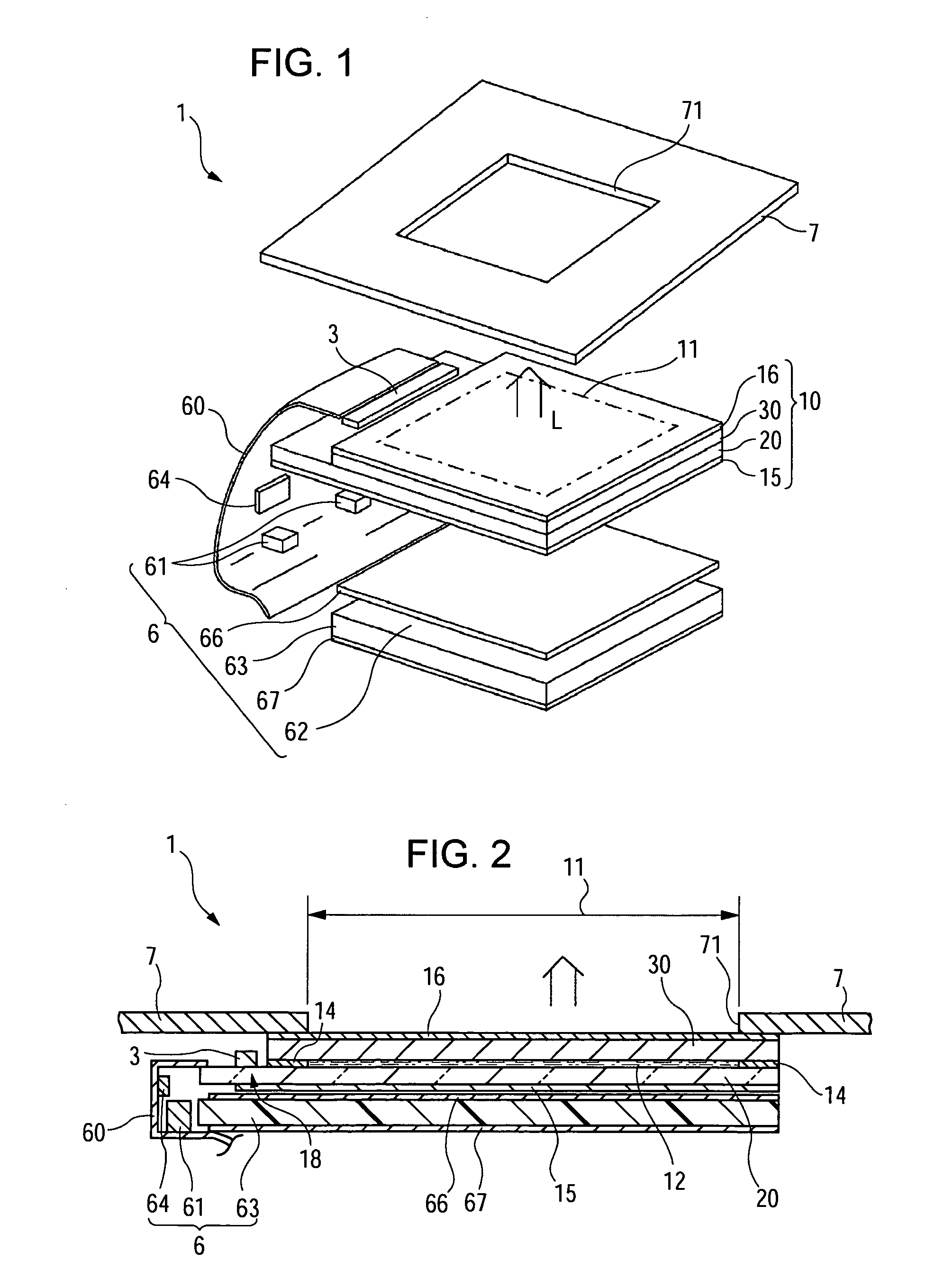
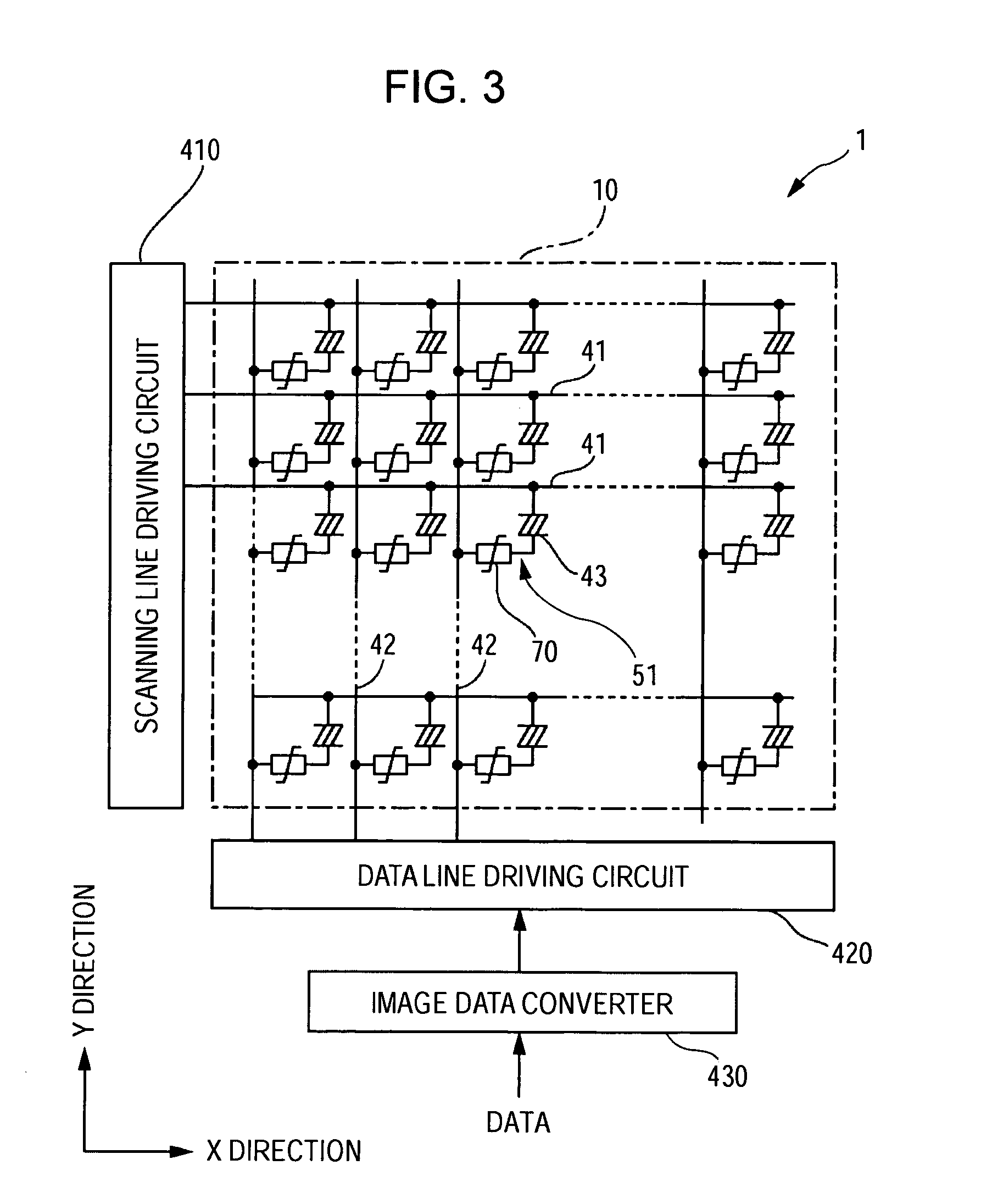
[0029]FIG. 1 is an exploded perspective view of an electro-optical device to which the invention is applied. FIG. 2 is a cross-sectional view of the electro-optical device shown in FIG. 1. FIG. 3 is a block diagram showing an electrical configuration of the electro-optical device shown in FIG. 1. FIG. 4 is an explanatory view showing a configuration of a pixel in plan view, in an electro-optical device according to a first embodiment of the invention. In FIG. 4, although a pixel-electrode is formed to cover a TFD element, a part of the pixel electrode is cut away to show the TFD element so that the presence of a component can be easily understood.

[0030]As shown in FIGS. 1 and 2, an electro-optical device 1 according to the present embodiment includes a backlight 6, an electro-optical panel 10, and a light-shielding frame 7, which are stacked in the above order. The frame 7 includes a light transmissive area 71 formed corresponding to an...

second embodiment

[0054]FIG. 6 is an explanatory view showing a configuration of a pixel, in plan view, in an electro-optical device according to a second embodiment of the invention.

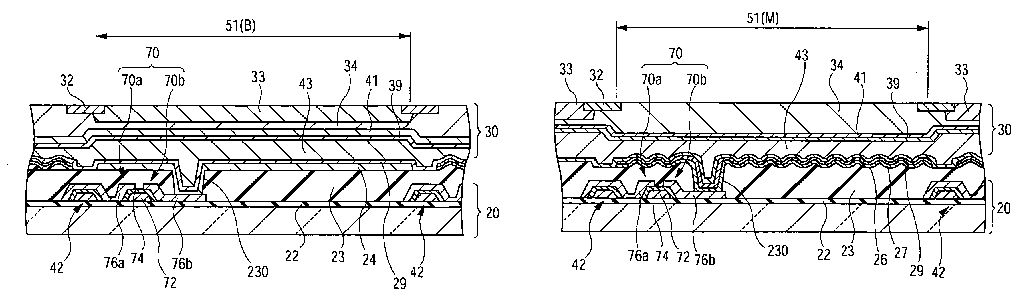
[0055]As shown in FIG. 6, in the electro-optical device according to the present embodiment, rows (X direction), on which three color-display sub-pixels 51(R), 51(G), and 51(B) are repeatedly arranged along the scanning line 41, and rows (X direction), on which monochrome-display sub-pixels 51(M) are arranged along the scanning line 41, are alternately arranged in a direction (Y direction) in which the data lines 42 are extended. The respective sub-pixels 51(R), 51(G), 51(B), and 51(M) have the same area. The configuration or operation of each sub-pixel 51(R), 51(G), 51(B), and 51(M) is the same as in the first embodiment and a detailed description thereof will thus be omitted herein.

[0056]Also in the present embodiment, the color-display sub-pixels 51(R), 51(G), and 51(B) display images in a transmissive mode in which l...

third embodiment

[0057]FIG. 7 is an explanatory view showing a configuration of a pixel, in plan view, in an electro-optical device according to a third embodiment of the invention.

[0058]As shown in FIG. 7, in the electro-optical device according to the present embodiment, rows (x direction), on which three color-display sub-pixels 51(R), 51(G), and 51(B) are repeatedly arranged along the scanning line 41, and rows (X direction), on which monochrome-display sub-pixels 51(M) having an area three times as large as that of the sub-pixel 51(R), 51(G), and 51(B) are arranged along the scanning line 41, are alternately arranged in a direction (Y direction) in which the data lines 42 are extended. The respective sub-pixels 51(R), 51(G), and 51(B) have the same area. Also, the color-display sub-pixels 51(R), 51(G), and 51(B) are respectively connected to the data line 42 through a single TFD element 70, while the monochrome-display sub-pixel 51(M) is connected to the data line 42 through three TFD elements ...


PUM

PropertyMeasurementUnit
thicknessaaaaaaaaaa
areaaaaaaaaaaa
color imagesaaaaaaaaaa

Abstract

There is provided an electro-optical device including pixels arranged in a matrix, each pixel having a plurality of color-display sub-pixels corresponding to a plurality of colors and a monochrome-display sub-pixel. The color-display sub-pixel and the monochrome-display sub-pixel can perform gray-scale display independently. One of the color-display sub-pixel and the monochrome-display sub-pixel displays images in a transmissive mode in which light emitted from a light source is modulated, while the other sub-pixel displays images in a reflective mode in which light incident from outside is modulated.

Description

RELATED APPLICATIONS[0001]This application claims priority to Japanese Patent Application No. 2004-253840 filed Sep. 1, 2004 which is hereby expressly incorporated by reference herein in its entirety.BACKGROUND OF THE INVENTION[0002]1. Technical Field[0003]The present invention relates to an electro-optical device capable of displaying images in transmissive and reflective modes, and to an electronic apparatus having the electro-optical device.[0004]2. Related Art[0005]In active-matrix-type electro-optical devices, pixels having a plurality of color-display sub-pixels respectively corresponding to a plurality of colors are arranged in a matrix. Also, images can be displayed in transmissive and reflective modes if a reflective layer is formed on each sub-pixel and a light transmissive portion is formed by removing a part of the reflective layer (for example, see Japanese Unexamined Patent Application Publication No. 2004-77544).[0006]However, a transflective electro-optical device di...

Claims


Application Information

Patent Timeline
Patent Type & Authority Patents(United States)
IPC IPC(8): G09G3/34G06F3/038G02F1/1335
CPCG02F1/133514G02F1/133555G09G3/367G02F2201/52G02F2203/30G09G2300/0439
Inventor KAMIJO, KIMITAKATAKIZAWA, KEIJI
Owner BOE TECH GRP CO LTD
Why Eureka
Try Eureka