Apparatus and method for determining pilot pattern in a broadband wireless access communication system

a communication system and broadband wireless technology, applied in the field of apparatus and method for determining pilot pattern in a broadband wireless access communication system, can solve the problem of difficult to ensure optimum performance over these random channels with the conventional fixed pilot pattern

Inactive Publication Date: 2010-09-07
SAMSUNG ELECTRONICS CO LTD +1
View PDF45 Cites 16 Cited by
  • Summary
  • Abstract
  • Description
  • Claims
  • Application Information

AI Technical Summary

Benefits of technology

[0011]An object of the present invention is to provide an apparatus and method for selecting a pilot pattern that minimizes channel estimation errors in a BWA communication system.

Problems solved by technology

Radio channels are said to be a wide range of random channels and it is difficult to always ensure optimum performance over these random channels with the conventional fixed pilot pattern.

Method used


Image

  • Apparatus and method for determining pilot pattern in a broadband wireless access communication system
  • Apparatus and method for determining pilot pattern in a broadband wireless access communication system
  • Apparatus and method for determining pilot pattern in a broadband wireless access communication system

Examples


first embodiment

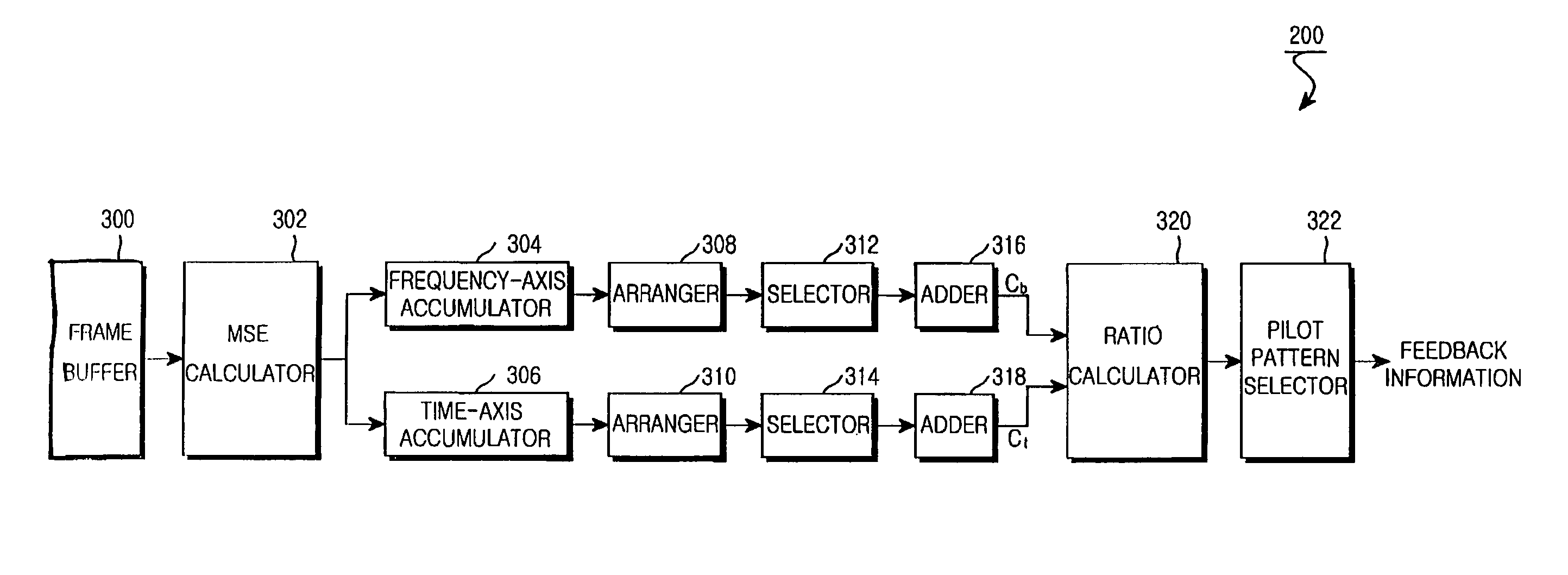
[0062]FIG. 5 is a graph illustrating a pilot pattern selection method according to the present invention. A 64×64 frame size and mapping of 64 pilot symbols per frame are assumed.

[0063]Referring to FIG. 5, a pilot pattern is selected in which the ratio R (Cb / Ct) converges to 1. If the coherence bandwidth is greater than the coherence time, the 16×4 first pilot pattern is selected in which pilot symbols are mapped at an interval of 16 along the frequency axis and at an interval of 4 along the time axis. If the coherence time is greater than the coherence bandwidth, the 4×16 second pilot pattern is selected in which pilot symbols are mapped at an interval of 4 along the frequency axis and at an interval of 16 along the time axis. In this manner, although the same number of pilot symbols are allocated to each frame, the layout of the pilot symbols is adapted to the link status.

second embodiment

[0064]FIG. 6 is a graph illustrating a pilot pattern selection method according to the present invention.

[0065]Referring to FIG. 6, two thresholds are set for pilot pattern switching. If the ratio R (Cb / Ct) is greater than a first threshold, the 16×4 first pilot pattern is selected. If the ratio R is between the first and second thresholds, an 8×8 third pilot pattern is selected in which pilot symbols are mapped at an interval of 8 along the frequency axis and at an interval of 8 along the time axis. If the ratio R is less than the second threshold, the 4×16 second pilot pattern is selected. This pilot pattern selection method leads to robust operation against factors such as sudden channel changes or frame delay by use of a smooth transitional pattern. Preferably, the first and second thresholds are empirically obtained.

[0066]A simulation was performed to verify the performance of the present invention, under the following parameters listed in Table 1.

[0067]

TABLE 1Carrier frequency...


PUM


Abstract

An apparatus and method for determining a pilot pattern in a Broadband Wireless Access (BWA) communication system are provided. In the pilot pattern determining method, an Orthogonal Frequency Division Multiplexing (OFDM) demodulator generates frequency-domain data by fast-Fourier-transform (FFT)-processing a received signal. A pilot pattern decider calculates a coherence bandwidth and a coherence time using subcarrier values received from the OFDM demodulator, and selects one of a plurality of pilot patterns according to the ratio of the coherence bandwidth to the coherence time.

Description

PRIORITY[0001]This application claims priority under 35 U.S.C. §119 to an application filed in the Korean Intellectual Property Office on Dec. 29, 2005 and assigned Serial No. 2005-132859, the contents of which are incorporated herein by reference.BACKGROUND OF THE INVENTION[0002]1. Field of the Invention[0003]The present invention relates generally to a Broadband Wireless Access (BWA) communication system, and in particular, to an apparatus and method for adaptively changing a pilot pattern according to a link in an Orthogonal Frequency Division Multiplexing (OFDM) communication system.[0004]2. Description of the Related Art[0005]Although there are many wireless communication technologies proposed as candidates for high-speed mobile communications, OFDM is considered the most prominent future-generation wireless communication technology. It is expected that OFDM will be adopted for most wireless communication applications by the year 2010. OFDM has been adopted as a standard for an...

Claims


Application Information

Patent Timeline
Patent Type & Authority Patents(United States)
IPC IPC(8): H04K1/10
CPCH04L27/261H04L1/0001H04L25/0222H04L27/26
Inventor LEE, JONG-HYEUKCHO, MYEON-KYUNPAIK, WON-KYUSEO, JONG-SOO
Owner SAMSUNG ELECTRONICS CO LTD
Why Eureka
Try Eureka