
Shoe sole

a technology of soles and shoes, applied in the field of shoes, can solve the problems of chronic tension, inflammation of various foot joints, and affecting the natural design of the soles of traditional shoes, and achieve the effect of reducing the number of shoes

Inactive Publication Date: 2010-09-14
CHAPMAN STEVEN
View PDF22 Cites 31 Cited by
  • Summary
  • Abstract
  • Description
  • Claims
  • Application Information

AI Technical Summary

Benefits of technology

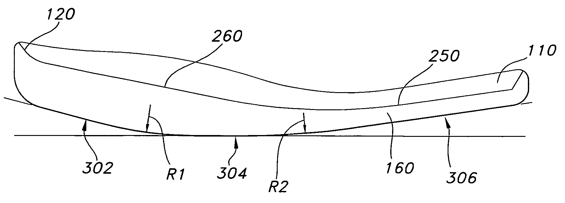
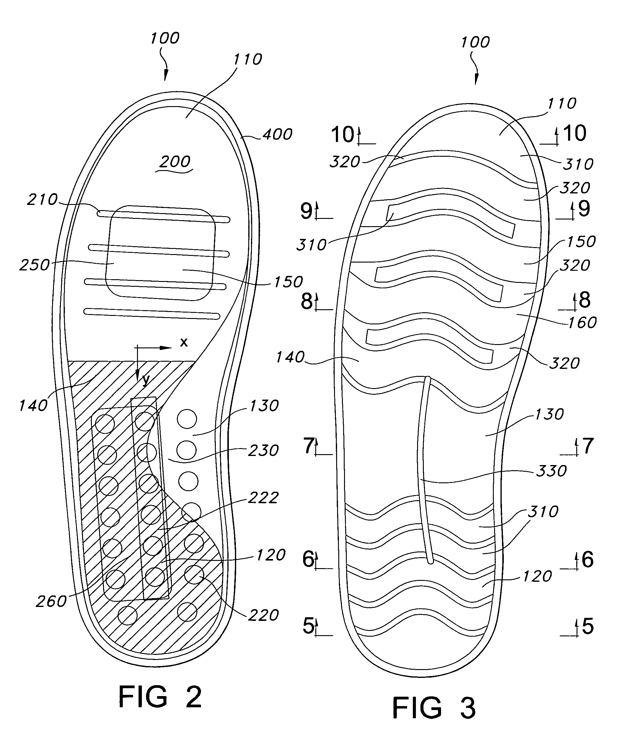
[0011]The upper surface of the shoe sole is a multi-planed formed surface that supports the entire bottom of the foot and maintains the foot in proper alignment, while allowing the foot to roll naturally from side to side and from heel to toe throughout the step motion. The upper surface has a heel section, an arch section, a ball section, and a toe section. The arch section rises above the level of other areas on the upper surface and supports the arch throughout the entire step. The ball section has a depression that cradles the ball of the foot. The toe area aligns the toes properly, particularly the first toe, so that it is in proper position to push the foot away from the walking surface.

Problems solved by technology

Traditional shoe soles cancel much of this natural design.
This orientation of the foot distorts the natural interaction of certain foot joints and ligaments and results in chronic tension that leads to inflammation of various foot joints.
The joints and ligaments are not in their natural and intended orientations and, as a result, the toe cannot push the foot away from the walking surface naturally.
Too much weight is placed on the heel.
This overloads certain joints in the foot and causes bone spurs and other problems in the heel.
The shift in the center of gravity also typically causes misalignment of the knees and of the hips.
Many of the muscles intended to be used in walking are not used properly and, as a result, atrophy from lack of use.
This chronic misalignment of the foot during walking leads to foot fatigue and the development of chronic postural problems, with the result that many people complain of problems with their feet, ankles, knees, and even lower spine.
This type of sole creates tension in other parts of the foot and lower spine and does not promote a natural gait.
Thus, the sole does not support the arch or the toes.
This insole is typically made of a soft, cushioning material, and does not provide the even, continuous support along the bottom of the foot that is needed when walking.

Method used


Image

  • Shoe sole
  • Shoe sole
  • Shoe sole

Examples


Embodiment Construction

[0028]The present invention will now be described more fully in detail with reference to the accompanying drawings, in which the preferred embodiment of the invention is shown. This invention should not, however, be construed as limited to the embodiment set forth herein; rather, the drawings are provided so that this disclosure will be complete and will fully convey the scope of the invention to those skilled in the art.

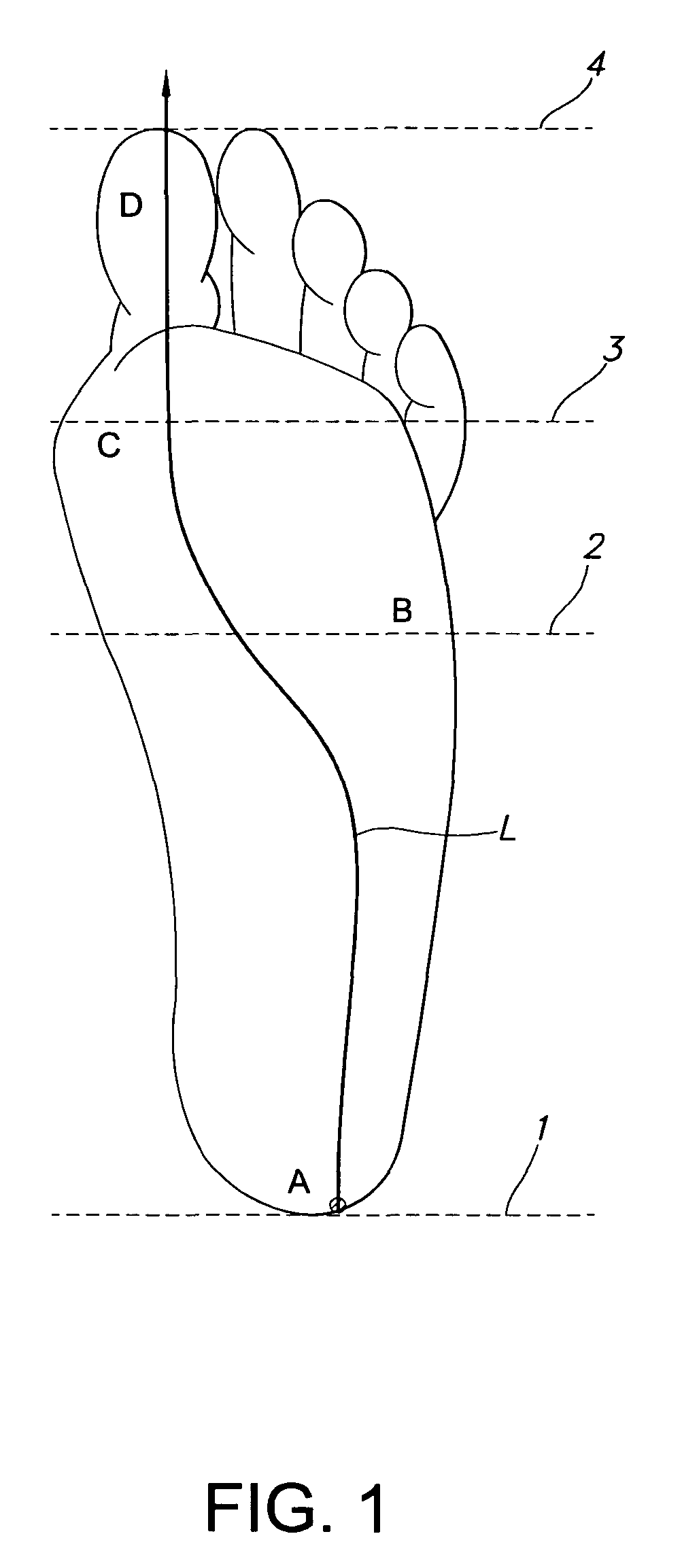
[0029]FIGS. 11 and 1 illustrate the natural motion of the foot through a complete walking step, from 11A through 11D. The upper portion of FIG. 11 shows a foot going through the walking step; the lower portion shows how the body weight is shifted along the sole of the foot. The areas A through D in FIG. 11 correspond to the similarly marked areas in FIG. 1. The shift in center of gravity is illustrated generally by line L in FIG. 1. The foot first comes into contact with a walking surface at 1 and rolls in a forward direction from heel A at 1 to toe D at 4, where th...


PUM


Abstract

Shoe sole that promotes a natural walking gait by promoting the natural step motion of a barefoot person walking in sand. The shoe sole has is a single-shot injection molded sole that has a continuously, irregularly curved lower surface and a multi-contoured upper surface. The lower surface has a radius of curvature in the heel area that is smaller than the radius of curvature in the toe area. The upper surface has an arch support, a depression for cradling the ball of the foot, and flex zones that promote flexing of the shoe sole in the longitudinal and transverse direction.

Description

BACKGROUND INFORMATION[0001]1. Field of the Invention[0002]The invention relates to the field of shoes. More particularly, the invention relates to shoe soles.[0003]2. Description of the Prior Art[0004]The natural design of the foot enables a smooth rolling motion throughout a step when walking. Studies of people's footprints in sand show that the foot rolls from heel to toe and, at the same time, also from an outside slant (supination) to an inside slant (pronation), in a smooth rolling motion. The step begins with setting the heel down on the walking surface and ends with the large toe pushing the foot off the walking surface. The toe at the end of the step and the heel at the beginning of the step are on the same plane. The center of gravity of the person is applied forward of the ankle, so that, in a normal standing position, the greatest portion of body weight is borne by the front portion of the foot, i.e., the ball and toes, and not the heel.[0005]Traditional shoe soles cance...

Claims


Application Information

Patent Timeline
Patent Type & Authority Patents(United States)
IPC IPC(8): A43B13/14A43B3/12
CPCA43B7/141A43B7/24A43B13/10A43B13/12A43B13/145
Inventor CHAPMAN, STEVENDUTILLY, ROGER C.SINGH, PAVAN
Owner CHAPMAN STEVEN
Learn More