Gear cutting machine, in particular bevel gear cutting machine, having a device for chamfering / deburring the edges of a work piece

a cutting machine and bevel gear technology, applied in the direction of gear teeth, gear manufacturing apparatus, manufacturing tools, etc., can solve the problem of high effort and achieve the effect of simple and reliable manner

Inactive Publication Date: 2010-09-14
GLEASON WORKS
View PDF24 Cites 16 Cited by
  • Summary
  • Abstract
  • Description
  • Claims
  • Application Information

AI Technical Summary

Benefits of technology

[0007]In the gear cutting machine in accordance with the invention, the chamfer / deburr apparatus and tool are fastened to a fixed component of the gear cutting machine. In this way, it is possible to adjust the chamfering / deburring tool into the working position in a simple and dependable manner to remove the edges at the bevel gear. The device preferably has a linear track as well as a pivot axis, which can position the tool into the optimum position for the chamfering and / or deburring of the bevel gear.

Problems solved by technology

This requires a high effort.

Method used


Image

  • Gear cutting machine, in particular bevel gear cutting machine, having a device for chamfering / deburring the edges of a work piece
  • Gear cutting machine, in particular bevel gear cutting machine, having a device for chamfering / deburring the edges of a work piece
  • Gear cutting machine, in particular bevel gear cutting machine, having a device for chamfering / deburring the edges of a work piece

Examples


Embodiment Construction

[0011]The invention is explained in greater detail by means of preferred embodiments which illustrate the invention by way of example only.

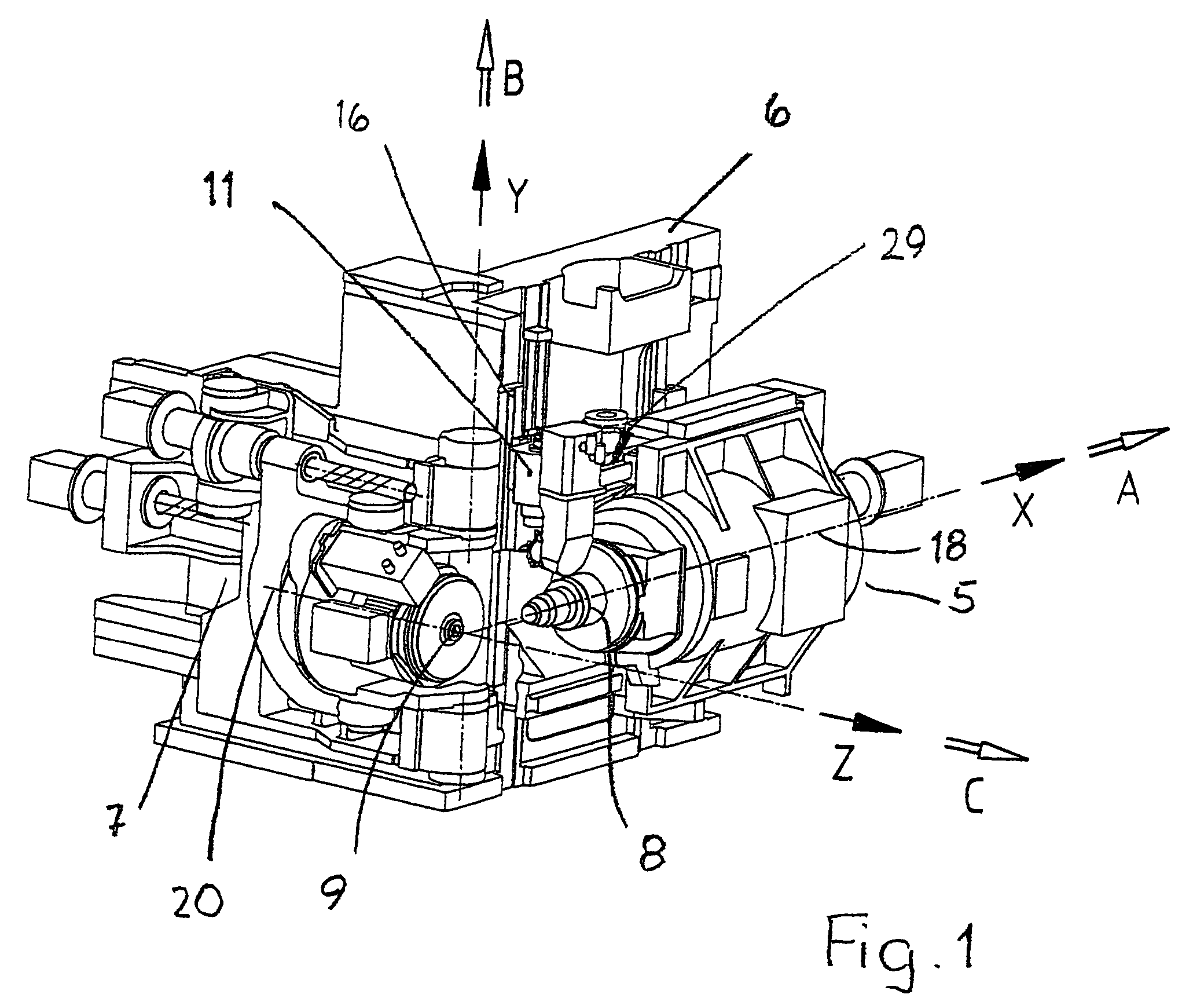
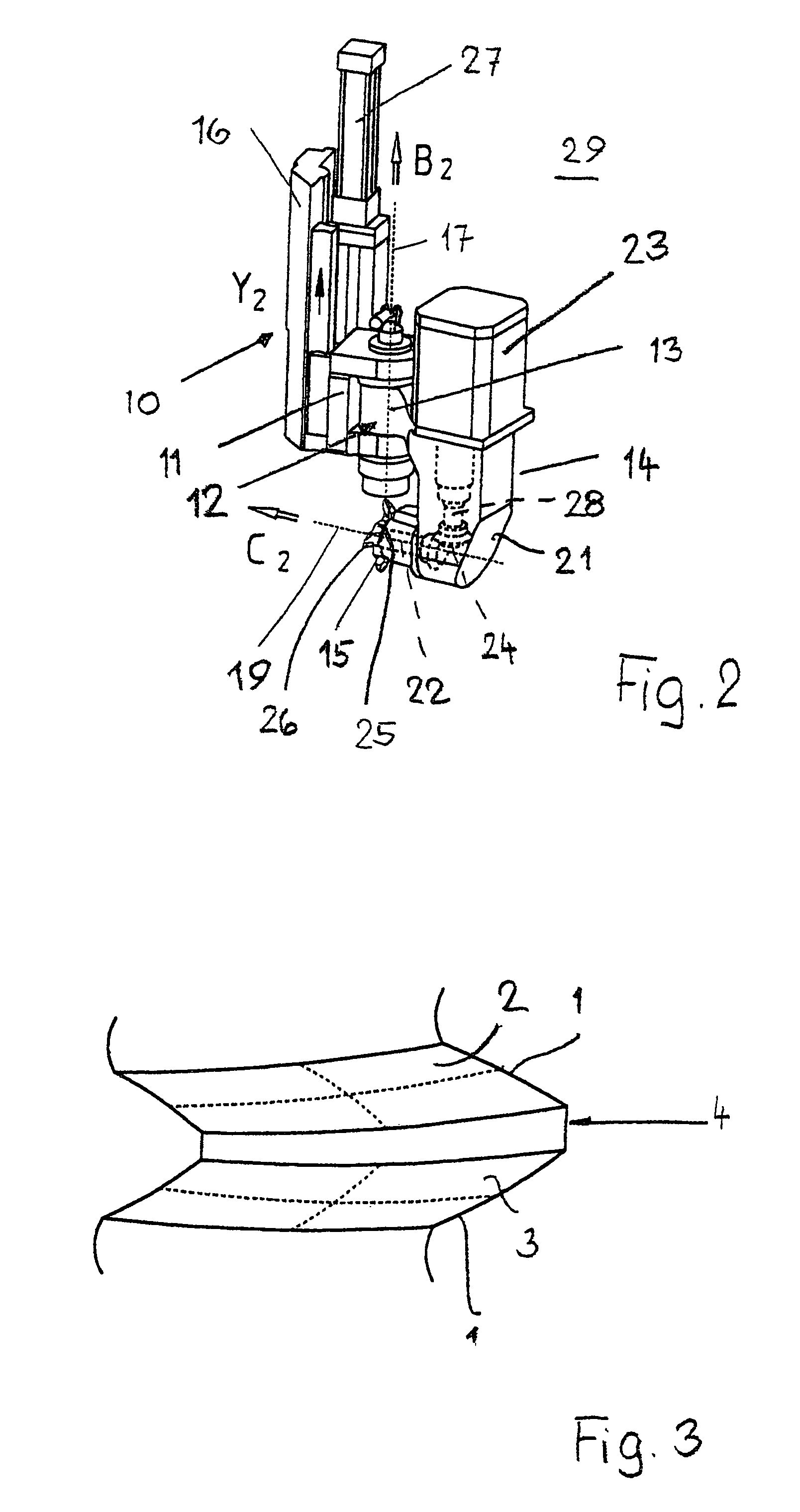
[0012]The device described in the following is used to chamfer and / or deburr the edges 1 between the flanks 2, 3 (FIG. 3) and a back face 4 (obscured in FIG. 3) of a bevel gear. It is also possible to use the device to machine the areas of the edges 1 where the transitions of the flanks 2, 3 are possibly rounded toward the top (preferably the face cone corner) and / or toward the root (top- and / or root rounding).

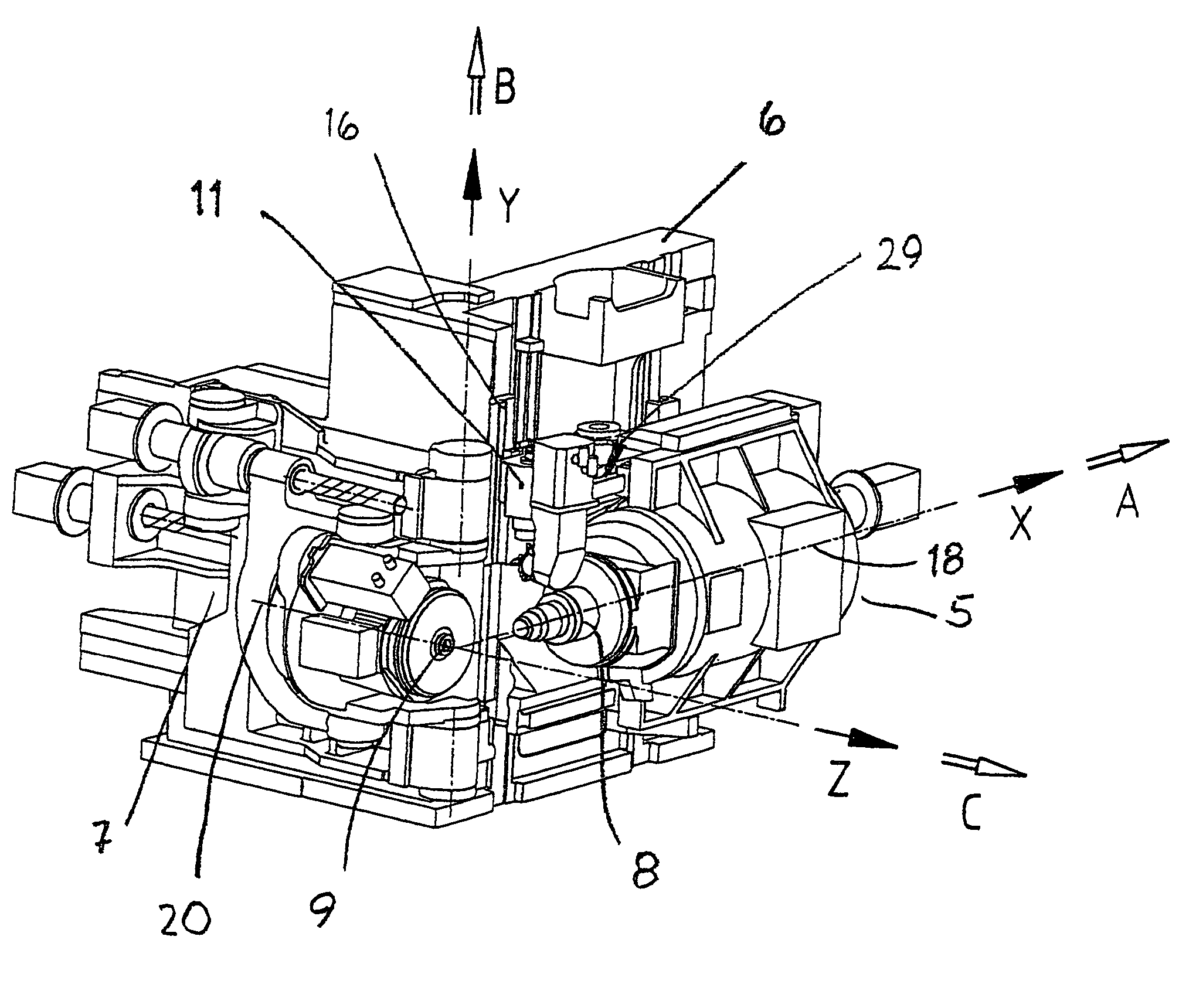
[0013]FIG. 1 shows a machine, such as shown in U.S. Pat. No. 6,712,566 to Stadtfeld et al. for example, with the device used for the chamfering and / or deburring provided at the machine, preferably on the machine stationary column or stand 6. The machine is a bevel gear cutting machine and has a work piece carriage 5 that can be moved in direction X (direction of the work piece axis of rotation 18). Furthermore, the work piece carriage 5 can...


PUM

PropertyMeasurementUnit
axis of rotationaaaaaaaaaa
specific angleaaaaaaaaaa
angleaaaaaaaaaa

Abstract

A gear cutting machine wherein a chamfer / deburr device and tool are fastened to a fixed component of the gear cutting machine. In this way, it is possible to adjust the chamfering / deburring tool into the working position in a simple and dependable manner to remove the edges from a gear. The device preferably has a linear track as well as a pivot axis, which can position the tool into the optimum position for the chamfering and / or deburring of the gear.

Description

[0001]This application claims the benefit of priority of German Utility Model Application No. DE 202005011790.0 filed Jul. 22, 2005.FIELD OF THE INVENTION[0002]The invention relates to a gear cutting machine, in particular bevel gear cutting machine, having a device to chamfer and / or deburr the edges between the flanks and the back face, in particular at the outer tooth ends, of a gear wheel produced in the gear cutting machine.BACKGROUND OF THE INVENTION[0003]With spiral-cut bevel gears, the flanks intersect with the back faces of the teeth at a specific angle. At the tooth, where the concave flank transitions into the back face, i.e., not observed on the gullet, the angle is an acute angle. At this point, an especially large burr is created during machining. The burr must be removed. In many cases, it is furthermore desired not only to remove the burr, but also to place a chamfer. With gears having this type of chamfer, the risk of injury during transport and installation is low a...

Claims


Application Information

Patent Timeline
Patent Type & Authority Patents(United States)
IPC IPC(8): B23F19/10B23F9/10B23F23/12
CPCB23F9/10B23F19/10B23F23/12Y10T409/108586Y10T409/101113Y10T409/106201B23F5/24B23F19/00B23F1/06
Inventor PEIFFER, KLAUSPHILIPPIN, MATTHIAS
Owner GLEASON WORKS
Why Eureka
Try Eureka