Rear drive type electric treadmill

a technology of electric treadmills and drives, applied in the direction of gymnastic exercise, sport apparatus, cardiovascular exercise devices, etc., can solve the problems of instant and temporary stagnation operator may feel repeated instant frustration, and achieve the effect of smooth operation of continuous moving belts

Inactive Publication Date: 2010-09-14
WANG LEAO
View PDF10 Cites 21 Cited by
  • Summary
  • Abstract
  • Description
  • Claims
  • Application Information

AI Technical Summary

Benefits of technology

[0006]A primary object of the invention is to provide a rear drive type electric treadmill wherein the force to rotate the continuous moving belt comes from a position behind an operator such that the driving force of the motor at the rear side can take away the force instantly acting on the continuous moving belt. In this way, the instant frustration may be removed and a smooth operation of the continuous moving belt is ensured.
[0007]According to the invention, a driving motor of a rear drive type electric treadmill is disposed at the rear end of a platform for directly driving a rear drum that is matched with a front drum so as to bring a continuous moving belt in a continuous movement. In this way, the force to rotate the continuous moving belt comes from a position behind an operator, thereby eliminating the frustration of the continuous moving belt each time when a force acts thereon. Moreover, a horizontal portion of a base frame has a slide recess facing to the platform. The platform is provided with a projecting wheel set at both sides thereof in match of the slide recesses. In this way, the platform is easily lifted upward in a vertical position. Consequently, it is beneficial for the operator to fold-up and move the treadmill.

Problems solved by technology

As a result, an instant and temporary stagnation of the continuous moving belt takes place since the continuous moving belt is subject to force suddenly (by the weight of the operator and the total gravity created during the exercise) each time when the operator treads on the continuous moving belt.
Thus, an instant frustration of the continuous moving belt occurs until the instant treading gravity is lessened or disappears.
Consequently, the operator may feel the repeated instant frustration from the continuous moving belt during a rapid and continuous walking exercise on the treadmill.
After all, this is a serious mistake in view of the product design.

Method used


Image

  • Rear drive type electric treadmill
  • Rear drive type electric treadmill
  • Rear drive type electric treadmill

Examples


Embodiment Construction

[0014]The present invention will now be described in more detail hereinafter with reference to the accompanying drawings that show a preferred embodiment of the invention.

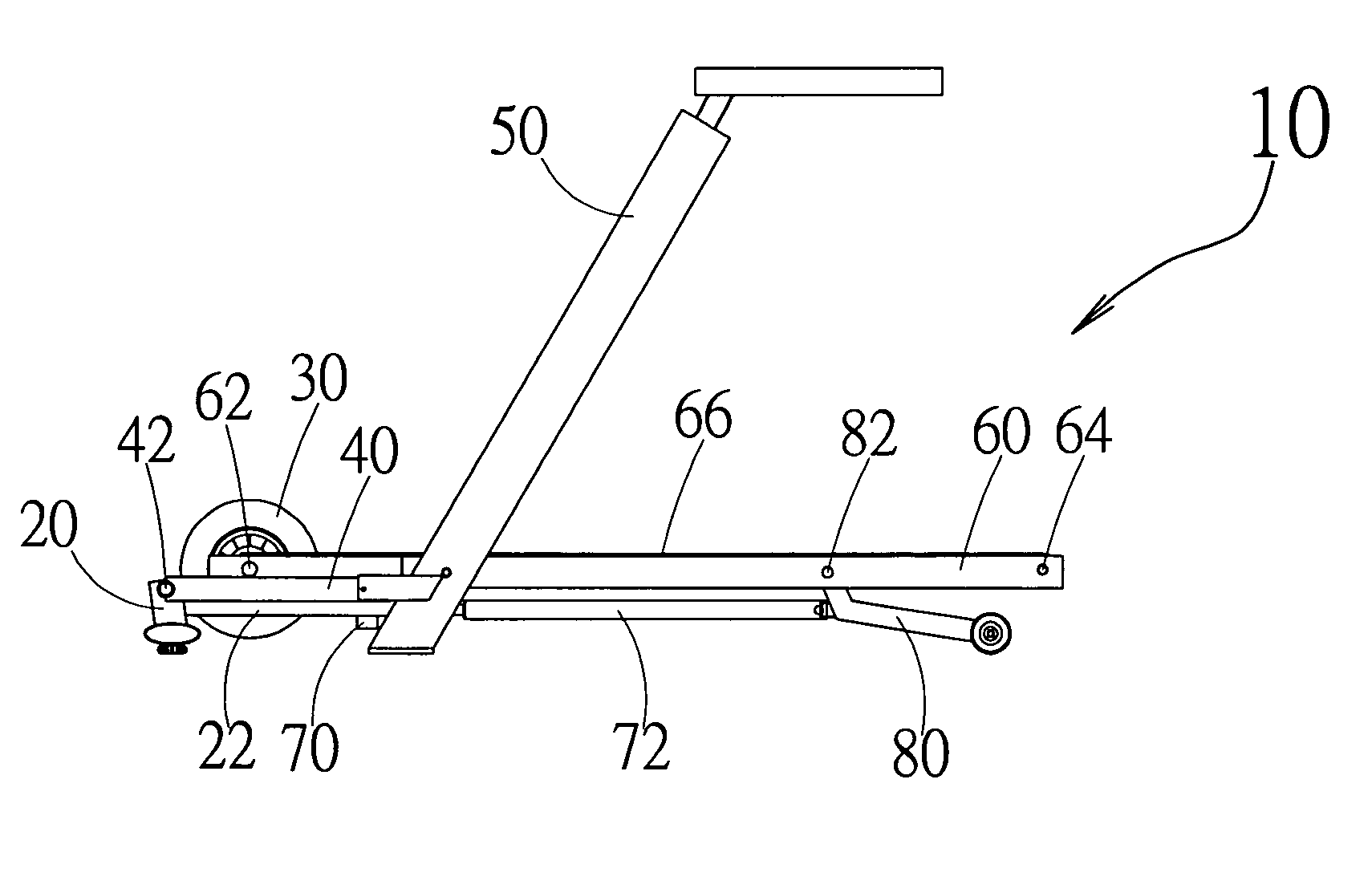
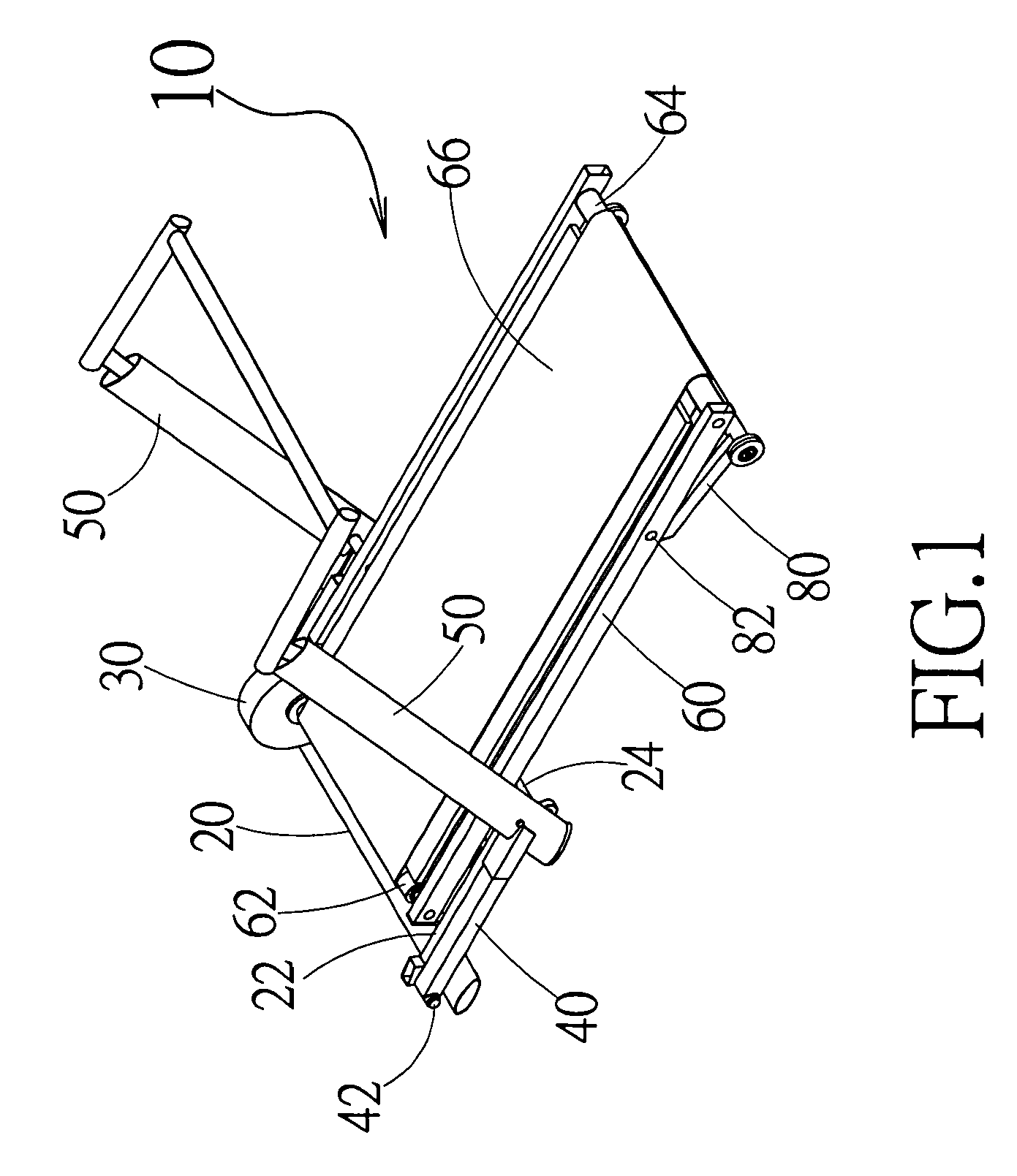
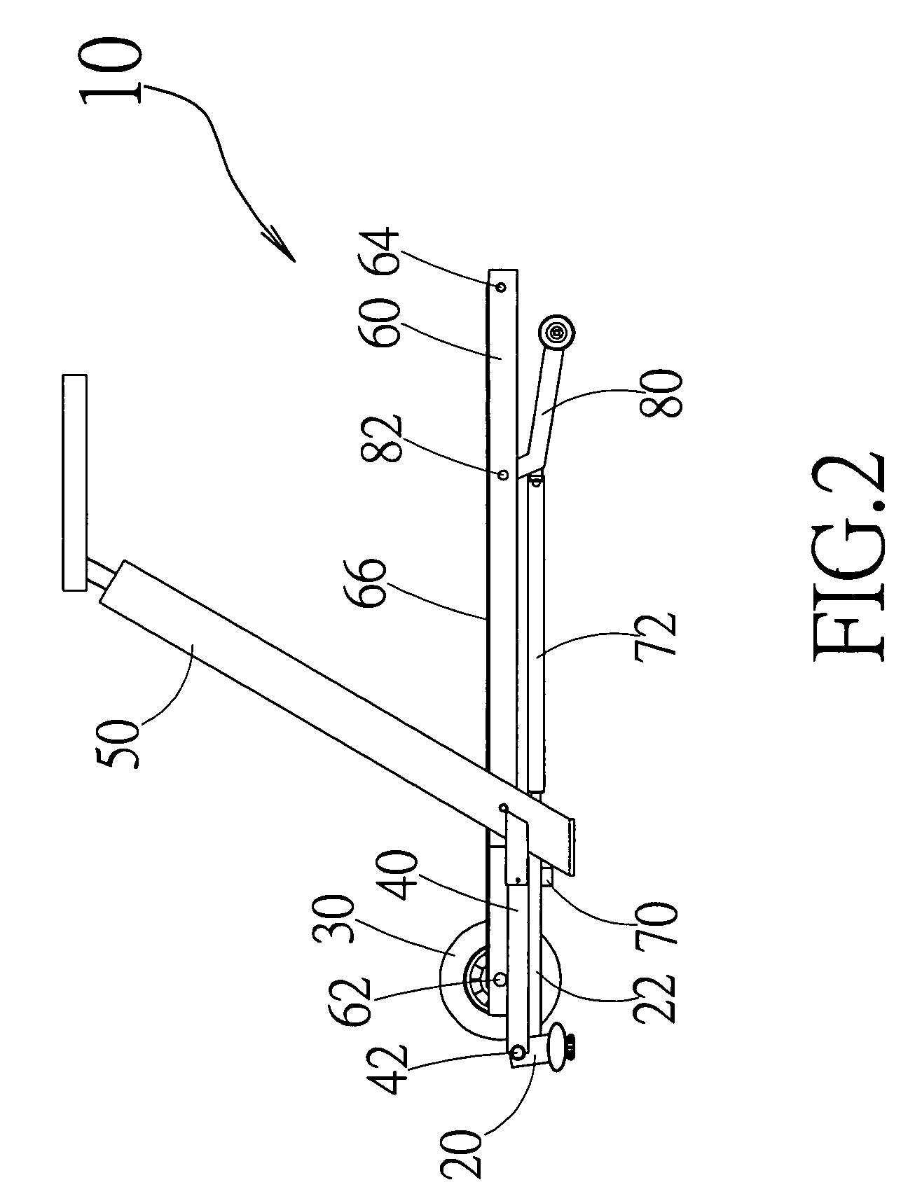
[0015]Referring to FIGS. 1 and 2, a treadmill 10 in accordance with of the invention includes a base frame 20, a driving motor 30, a handrail bracket 40, a handrail unit 50, a platform 60, a lifting motor 70, a lifting drive rod 72, and a front support 80. The driving motor 30 is disposed at the rear end of the platform 60 for directly driving a rear drum 62 that is matched with a front drum 64 so as to bring a continuous moving belt 66 in a continuous movement. In this way, the force to rotate the continuous moving belt 66 comes from a position behind an operator (not shown).

[0016]As shown in FIGS. 2 and 3, the lifting motor 70 and the lifting drive rod 72 are installed at the bottom of the platform 60 in such a manner that the front support 80 pivotally disposed near the front end of the platform 60 is swiveled a...


PUM


Abstract

A rear drive type electric treadmill wherein a driving motor is disposed at the rear end of a platform for directly driving a rear drum that is matched with a front drum so as to bring a continuous moving belt in a continuous movement. In this way, the force to rotate the continuous moving belt comes from a position behind an operator, thereby eliminating the frustration of the continuous moving belt each time when a force acts thereon. Moreover, a horizontal portion of the base frame has a slide recess facing to the platform. The platform is provided with a projecting wheel set at both sides thereof in match of the slide recesses. In this way, the platform is easily lifted upward in a vertical position. Consequently, it is beneficial for the operator to fold-up and move the treadmill.

Description

BACKGROUND OF THE INVENTION[0001]1. Fields of the Invention[0002]The invention relates to a rear drive type electric treadmill, and more particularly, to a structure that the force to rotate the continuous moving belt comes from a position behind an operator, thereby eliminating the frustration of the continuous moving belt each time when a force acts thereon. Meanwhile, the platform is easily lifted upward in a vertical position.[0003]2. Description of the Related Art[0004]As well-known, the conventional electric treadmills include a driving motor fitted at the front end of the continuous moving belt. Therefore, the force to rotate the continuous moving belt comes from a position before an operator. As a result, an instant and temporary stagnation of the continuous moving belt takes place since the continuous moving belt is subject to force suddenly (by the weight of the operator and the total gravity created during the exercise) each time when the operator treads on the continuous...

Claims


Application Information

Patent Timeline
Patent Type & Authority Patents(United States)
IPC IPC(8): A63B22/00
CPCA63B22/02A63B22/0235A63B22/0023A63B2210/50
Inventor WANG, LEAO
Owner WANG LEAO
Why Eureka
Try Eureka