Reaction arm for power-driven torque intensifier

a technology of torque intensifier and reaction arm, which is applied in the direction of wrenches, power driven tools, screwdrivers, etc., can solve the problem of limiting the rundown speed

Active Publication Date: 2010-09-21
HYTORC DIV UNEX CORP
View PDF11 Cites 46 Cited by
  • Summary
  • Abstract
  • Description
  • Claims
  • Application Information

AI Technical Summary

Benefits of technology

[0005]Accordingly, it is an object of the present invention to provide a reaction arm for a power-driven torque intensifier, as well as a power-driven torque intensifier with a reaction arm, which avoid the above mentioned disadvantages of the prior art.

Problems solved by technology

This brings along a problem that a run down speed needs to be limited to avoid that the reaction arm, that usually abuts against a nut adjacent to the nut to be tightened, is slammed against the nut at a high speed, which could cause an accident if the operator's fingers are in the way.
The same problem arises when a torque intensifier is used in a way that the gear mechanism and the gear housing turn at a given speed in the same direction for run down and run up, and in opposite directions to tighten or loosen a nut, because while an abutment of reaction arm is necessary for the second-mentioned mode of operation, it is not desirable for the first-mentioned mode of operation, again to avoid accidents.

Method used


Image

  • Reaction arm for power-driven torque intensifier
  • Reaction arm for power-driven torque intensifier

Examples


Embodiment Construction

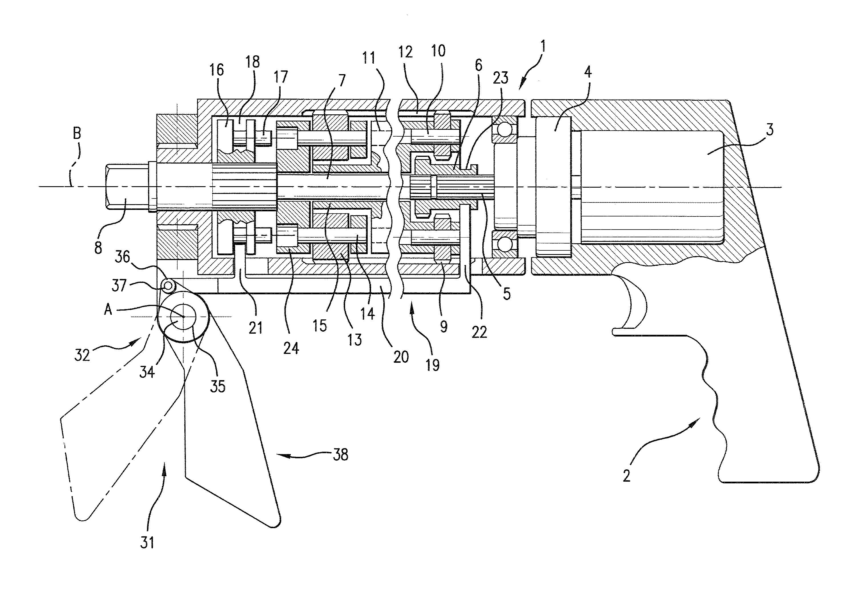
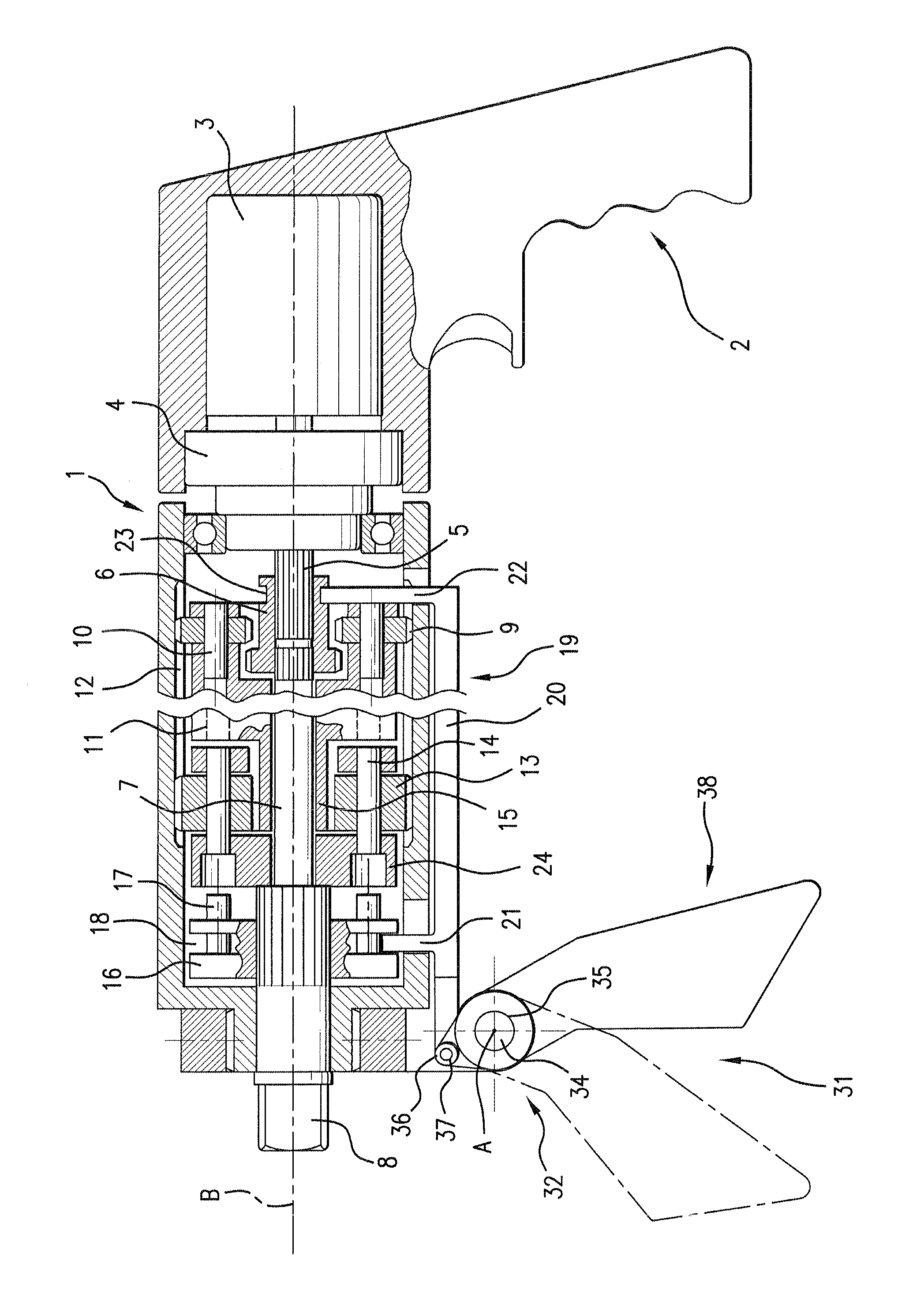
[0011]A power-driven torque intensifier shown in the drawings has a housing which is identified with reference numeral 1 and is provided with a handle 2. The torque intensifier has a motor 3, and a single stage gear multiplier 4, for example of a planetary type, which is driven by the motor 3 and has an output shaft 5.

[0012]A multi-stage planetary gear set is accommodated in the housing 1 and includes, for example, a first stage and a second stage. The first stage includes a sun gear 6 which internally engages with the output shaft 5 and is internally engageable with a drive shaft 7, for example by interengaging splines provided on an inner surface of the sun gear 6 and on outer surfaces of the output shaft 5 and the drive shaft 7. On its output end the drive shaft 7 has an engaging member formed, for example, as a square-shaped end portion 8. The first stage further has satellite gears 9, which are mounted on shafts 10 held in a carrier 11. The satellite gears 9 have outer surfaces...


PUM


Abstract

A reaction arm for a power-driven torque intensifier having a housing with an axis, a torque intensifier unit and a switching device for switching the torque intensifier unit between high speed / low torque and low speed / high torque, is configured for operating the switching device so that when the reaction arm is placed in a first position, the torque intensifier unit is switched to high speed / low torque and the reaction arm is usable as a handle by an operator, and when the reaction arm is placed in a second position the torque intensifier unit is switched to low speed / high torque and the reaction arm can abut against a stationary object since the high torque can not be absorbed by the operator.

Description

BACKGROUND OF THE INVENTION[0001]The present invention relates to reaction arms for power-driven torque intensifiers, as well as to power-driven torque intensifiers provided with reaction arms.[0002]Power-driven torque intensifiers or torque multipliers are available to be used with two speeds, including one high speed to run down a nut on a bolt or the like or to run up the nut, and one low speed to apply a high torque to the nut in order to tighten or loosen the nut.[0003]The torque intensifiers require the use of reaction means to divert a reaction force generated during turning of the nut, to a stationary object. This brings along a problem that a run down speed needs to be limited to avoid that the reaction arm, that usually abuts against a nut adjacent to the nut to be tightened, is slammed against the nut at a high speed, which could cause an accident if the operator's fingers are in the way.[0004]The same problem arises when a torque intensifier is used in a way that the gea...

Claims


Application Information

Patent Timeline
Patent Type & Authority Patents(United States)
IPC IPC(8): B25B21/00
CPCB25F5/026B25B23/0078B25F5/001B25F5/028B25B21/008B25B21/004B25B23/14B25B23/147B25B21/00
Inventor JUNKERS
Owner HYTORC DIV UNEX CORP
Why Eureka
Try Eureka