Wellbore surveying system and method

a surveying system and wellbore technology, applied can solve the problems of many sources of measurement uncertainty and inaccuracy, unpredictably affecting the actual trajectory of a wellbore, and the inherent uncertainty of global magnetic field in the field of wellbore surveying systems and techniques

Inactive Publication Date: 2010-09-21
SCHLUMBERGER TECH CORP
View PDF14 Cites 18 Cited by
  • Summary
  • Abstract
  • Description
  • Claims
  • Application Information

AI Technical Summary

Problems solved by technology

Directional wellbores are drilled through Earth formations according to a selected or desired trajectory, however, many factors may combine to unpredictably influence the actual trajectory of a wellbore.
There are many sources of measurement uncertainty and inaccuracy.
For example, magnetic measuring techniques suffer from the inherent uncertainty in global magnetic models used to estimate declination at a specific site, as well as local perturbations in the magnetic field due to the nearby magnetic materials or the casing of the wellbore or of a nearby well.
Similarly, gravitational measuring techniques suffer from movement of the downhole tool and uncertainties in the accelerometers.
Gyroscopic measuring techniques, for example, suffer from drift uncertainty.
Depth measurements are also prone to uncertainties including mechanical stretch from gravitational forces and thermal expansion, for example.

Method used


Image

  • Wellbore surveying system and method
  • Wellbore surveying system and method
  • Wellbore surveying system and method

Examples


Embodiment Construction

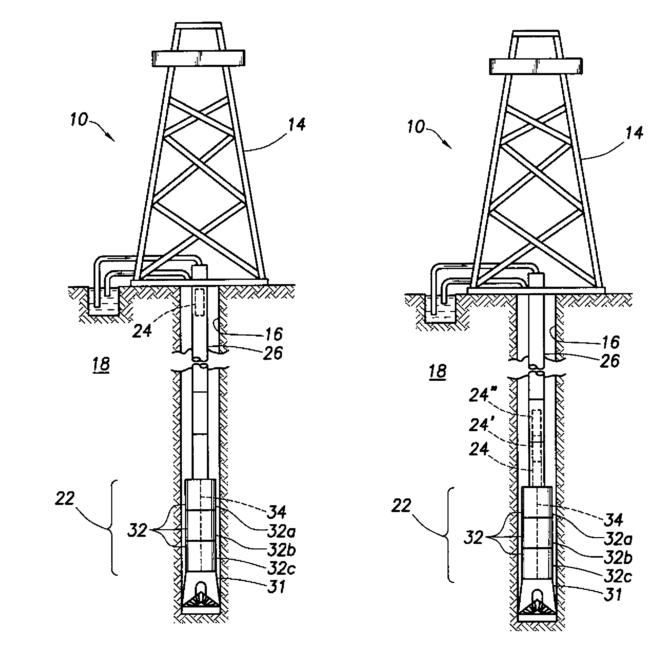
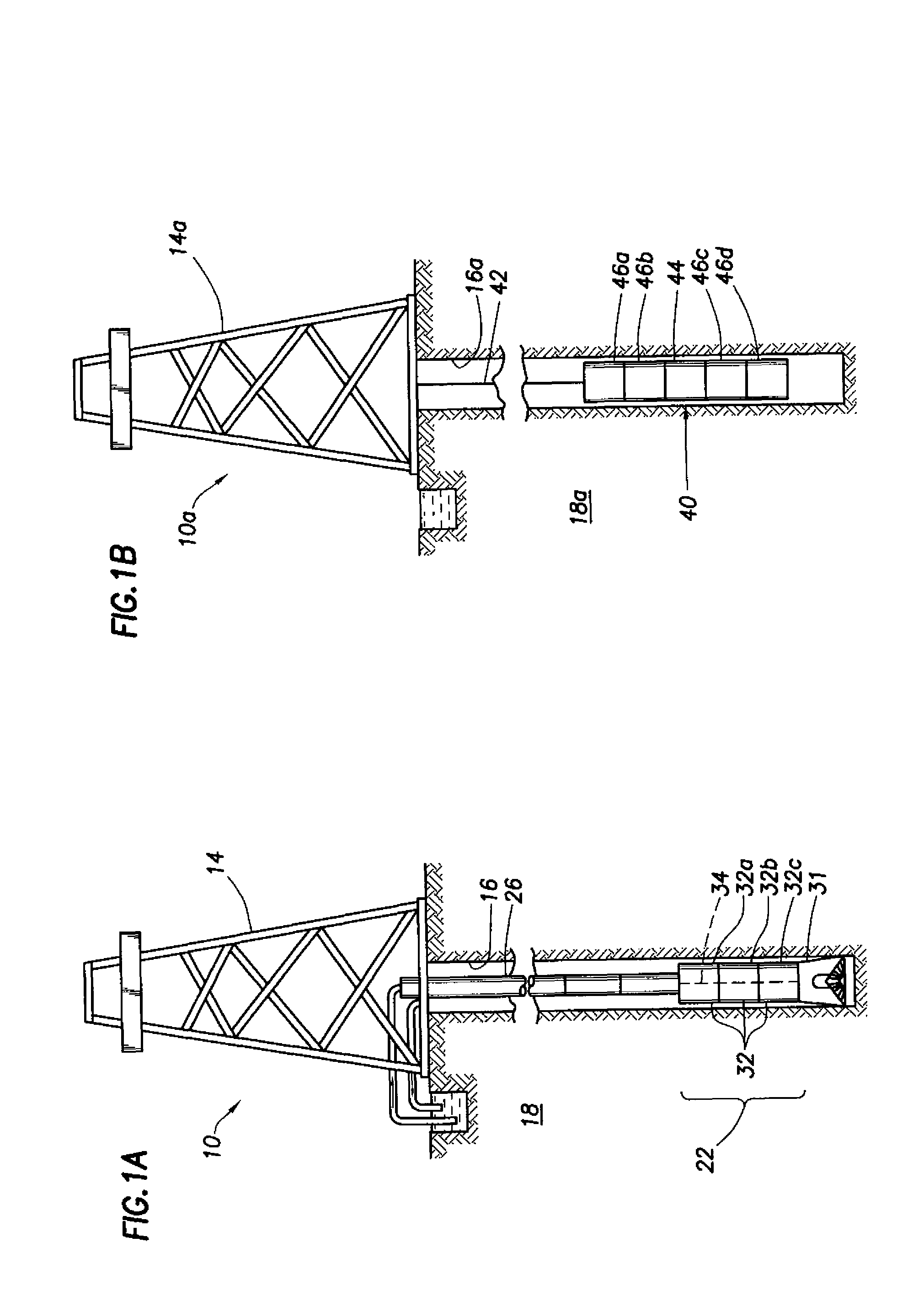
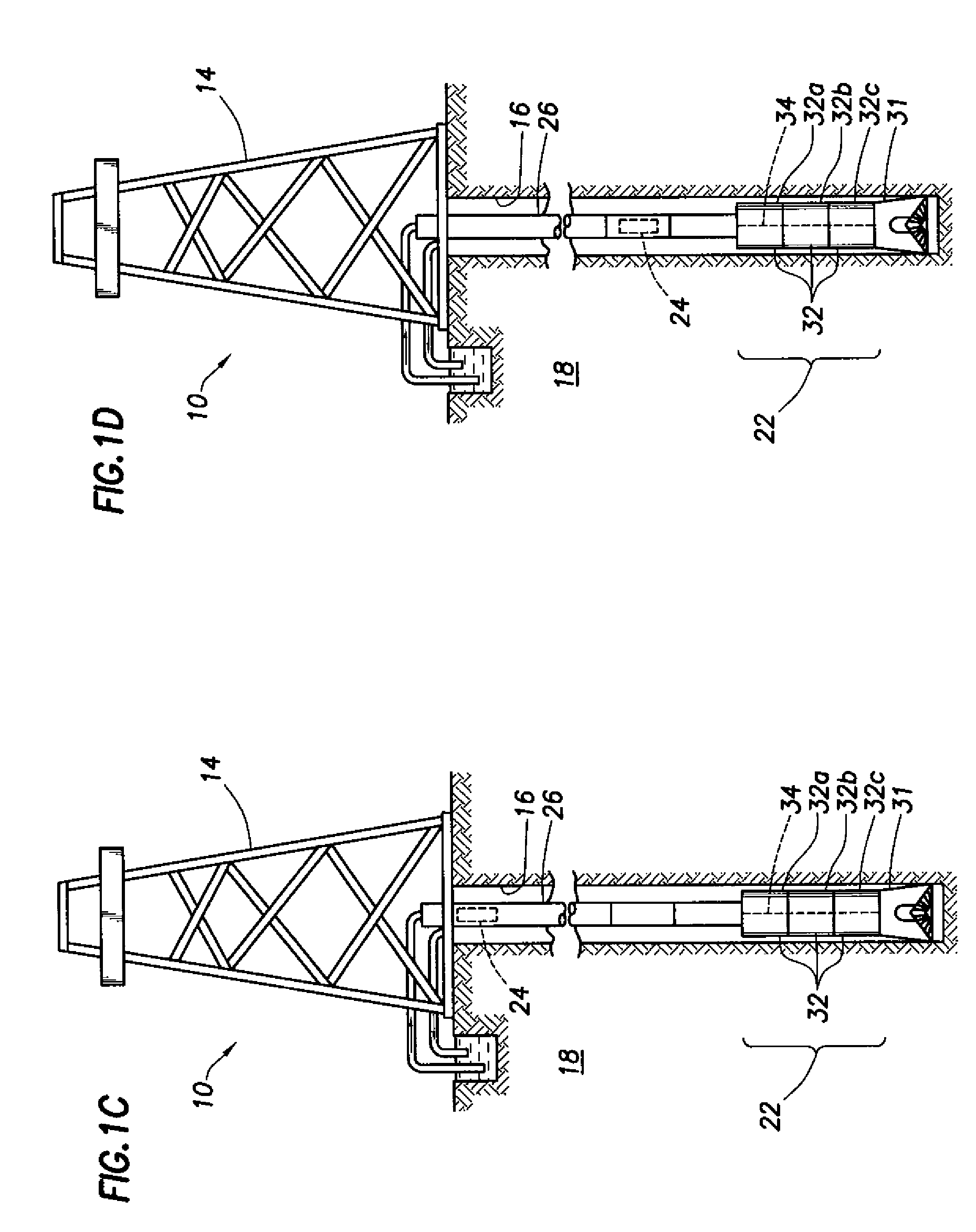
[0022]FIG. 1A shows one example of a drilling system 10 that includes a drilling rig 14 positioned above a wellbore 16 penetrating a subterranean formation 18. In general, the drilling system 10 is provided with a downhole drilling assembly 22 that includes one or more while-drilling tools or downhole components 32a-c and a drill bit 31. The downhole drilling assembly 22, sometimes called a bottom home assembly (“BHA”), may include any number and types of while-drilling tools, such as sensors, telemetry devices, and directional drilling tools. The downhole drilling assembly 22 may be deployed into the wellbore 16 from the rig 14 via a drill string 26. The downhole drilling assembly 22 may drill the wellbore 16 and may be operatively connected to the rig via the drill string 26.

[0023]The downhole drilling assembly 22 includes a drill bit 31, and a plurality of interconnected downhole components 32a-c. By way of example, these downhole components 32a-c are illustrated in FIG. 1A. The ...


PUM


Abstract

A method for surveying a wellbore may include deploying a deployable wellbore survey tool into the wellbore, collecting survey data as the deployable survey tool traverses the wellbore, and determining wellbore position information based on the survey data. In one example the method may include landing the deployable wellbore survey tool on a component of a bottom hole assembly.

Description

BACKGROUND OF THE INVENTION [0001]1. Field of the Invention[0002]The present invention relates to wellbore surveying systems and techniques. More particularly, the present invention relates to systems techniques for surveying wellbores and / or determining position of a wellbore in the Earth.[0003]2. Background of the Related Art[0004]Wellbores are drilled to locate and produce hydrocarbons. A downhole drilling tool with a bit at an end thereof is advanced into the ground to form a wellbore. As the drilling tool is advanced, a drilling mud is pumped from a surface mud pit, through the drilling tool and out the drill bit to cool the drilling tool and carry away cuttings. The fluid exits the drill bit and flows back up to the surface for recirculation through the tool. The drilling mud is also used to form a mudcake to line the wellbore.[0005]Fluids, such as oil, gas and water, are commonly recovered from subterranean formations below the earth's surface. Drilling rigs at the surface ar...

Claims


Application Information

Patent Timeline
Patent Type & Authority Patents(United States)
IPC IPC(8): E21B47/00E21B47/02
CPCE21B23/08E21B47/022E21B47/00E21B47/01
Inventor PHILLIPS, WAYNE J.CHIA, CHRISTOPHER R.WONG, RICHARD V. C.
Owner SCHLUMBERGER TECH CORP
Why Eureka
Try Eureka